Facebook Instagram Youtube Twitter

Velocity Head

In general, the hydraulic head, or total head, is a measure of fluid’s potential at the measurement point. It can be used to determine a hydraulic gradient between two or more points.
Bernoulli Theorem - Equation

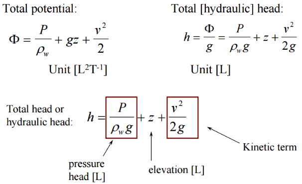
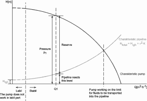
In fluid dynamics, the head is a concept that relates the energy in an incompressible fluid to the height of an equivalent static column of that fluid. The units for all the different forms of energy in Bernoulli’s equation can also be measured in distance units. Therefore these terms are sometimes referred to as “heads” (pressure head, velocity head, and elevation head). Head is also defined for pumps. This head is usually referred to as the static head and represents the maximum height (pressure) it can deliver. Therefore the characteristics of all pumps can usually be read from their Q-H curve (flow rate – height).

There are four types of potential (head):

  • Pressure potential – Pressure head: The pressure head represents the flow energy of a column of fluid whose weight is equivalent to the pressure of the fluid.Pressure Headρw: density of water assumed to be independent of pressure
  • Elevation potential – Elevation head: The elevation head represents the potential energy of a fluid due to its elevation above a reference level.Elevation Head
  • Kinetic potential – Kinetic head: The kinetic head represents the kinetic energy of the fluid. The height in feet is that a flowing fluid would rise in a column if all of its kinetic energy were converted to potential energy.Kinetic Head

The sum of a fluid’s elevation head, kinetic head, and pressure head is called the total head. Thus, Bernoulli’s equation states that the total head of the fluid is constant.
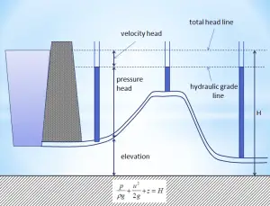
Total Hydraulic Head

Q-H characteristic diagram of centrifugal pump and of pipeline
Q-H characteristic diagram of centrifugal pump and pipeline
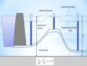
Hydraulic Head - Total Head Line
Piezometer levels when fluid is flowing. In this figure that the levels have been reduced by an amount equal to the velocity head.
Hydraulic Head - Velocity Head
Piezometer levels and velocity heads with fluid flowing in varying diameter pipes. The velocity head at each point is now different. This is because the velocity is different at each point.
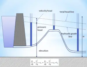
Hydraulic Head - Hydraulic Grade Line
Hydraulic grade line and Total headlines for a constant diameter pipe with friction. In a real pipeline, there are energy losses due to friction – these must be considered as they can be very significant.
 
Extended Bernoulli’s Equation
There are two main assumptions, that were applied on the derivation of the simplified Bernoulli’s equation.
  • The first restriction on Bernoulli’s equation is that no work is allowed to be done on or by the fluid. This is a significant limitation because most hydraulic systems (especially in nuclear engineering) include pumps. This restriction prevents two points in a fluid stream from being analyzed if a pump exists between the two points.
  • The second restriction on simplified Bernoulli’s equation is that no fluid friction can solve hydraulic problems. In reality, friction plays a crucial role. The total head possessed by the fluid cannot be transferred completely and is lossless from one point to another. In reality, one purpose of pumps incorporated in a hydraulic system is to overcome the losses in pressure due to friction.
Q-H characteristic diagram of centrifugal pump and of pipeline
Q-H characteristic diagram of centrifugal pump and pipeline

Due to these restrictions, most practical applications of the simplified Bernoulli equation to real hydraulic systems are very limited. The simplified Bernoulli equation must be modified to deal with both head losses and pump work.

The Bernoulli equation can be modified to take into account gains and losses of the head. The resulting equation, referred to as the extended Bernoulli’s equation is useful in solving most fluid flow problems. The following equation is one form of the extended Bernoulli equation.

Extended Bernoulli Equation

where:
h = height above reference level (m)
v = average velocity of fluid (m/s)
p = pressure of fluid (Pa)
Hpump = head added by pump (m)
Hfriction = head loss due to fluid friction (m)
g = acceleration due to gravity (m/s2)

The head loss (or the pressure loss) due to fluid friction (Hfriction) represents the energy used in overcoming friction caused by the pipe walls. The head loss that occurs in pipes is dependent on the flow velocity, pipe diameter, and length, and a friction factor based on the roughness of the pipe and the Reynolds number of the flow. A piping system containing many pipe fittings and joints, tube convergence, divergence, turns, surface roughness, and other physical properties will also increase the head loss of a hydraulic system.

Although the head loss represents a loss of energy, it does not represent a loss of total energy of the fluid. The total energy of the fluid is conserved as a consequence of the law of conservation of energy. In reality, the head loss due to friction results in an equivalent increase in the fluid’s internal energy (temperature increases).

Most methods for evaluating head loss due to friction are based almost exclusively on experimental evidence. This will be discussed in the following sections.

Consider a pipe containing an ideal fluid. Suppose this pipe undergoes a gradual expansion in diameter. In that case, the continuity equation tells us that as the pipe diameter increases, the flow velocity must decrease to maintain the same mass flow rate. Since the outlet velocity is less than the inlet velocity, the kinetic head of the flow must decrease from the inlet to the outlet. If there is no change in the elevation head (the pipe lies horizontally), the decrease in the kinetic head must be compensated for by an increase in pressure head.
 
Example: Frictional Head Loss
Water at 20°C is pumped through a smooth 12-cm-diameter pipe 10 km long, at a flow rate of 75 m3/h. The inlet is fed by a pump at an absolute pressure of 2.4 MPa.
The exit is at standard atmospheric pressure (101 kPa) and is 200 m higher.

Calculate the frictional head loss Hf and compare it to the velocity head of the flow v2/(2g).

Solution:

Since the pipe diameter is constant, the average velocity and velocity head is the same everywhere:

vout = Q/A = 75 [m3/h] * 3600 [s/h] / 0.0113 [m2] = 1.84 m/s

Velocity head:

Velocity head = vout2/(2g) = 1.842 / 2*9.81 = 0.173 m

In order to find the frictional head loss, we have to use extended Bernoulli’s equation:

Extended Bernoulli Equation

Head loss:

2 400 000 [Pa] / 1000 [kg/m3] * 9.81 [m/s2]  + 0.173 [m] + 0 [m] = 101 000 [Pa] / 1000 [kg/m3] * 9.81 [m/s2] + 0.173 [m]+ 200 [m] + Hf

H = 244.6 – 10.3 – 200 = 34.3 m

 
References:
Reactor Physics and Thermal Hydraulics:
  1. J. R. Lamarsh, Introduction to Nuclear Reactor Theory, 2nd ed., Addison-Wesley, Reading, MA (1983).
  2. J. R. Lamarsh, A. J. Baratta, Introduction to Nuclear Engineering, 3d ed., Prentice-Hall, 2001, ISBN: 0-201-82498-1.
  3. W. M. Stacey, Nuclear Reactor Physics, John Wiley & Sons, 2001, ISBN: 0- 471-39127-1.
  4. Glasstone, Sesonske. Nuclear Reactor Engineering: Reactor Systems Engineering, Springer; 4th edition, 1994, ISBN: 978-0412985317
  5. Todreas Neil E., Kazimi Mujid S. Nuclear Systems Volume I: Thermal Hydraulic Fundamentals, Second Edition. CRC Press; 2 edition, 2012, ISBN: 978-0415802871
  6. Zohuri B., McDaniel P. Thermodynamics in Nuclear Power Plant Systems. Springer; 2015, ISBN: 978-3-319-13419-2
  7. Moran Michal J., Shapiro Howard N. Fundamentals of Engineering Thermodynamics, Fifth Edition, John Wiley & Sons, 2006, ISBN: 978-0-470-03037-0
  8. Kleinstreuer C. Modern Fluid Dynamics. Springer, 2010, ISBN 978-1-4020-8670-0.
  9. U.S. Department of Energy, THERMODYNAMICS, HEAT TRANSFER, AND FLUID FLOW. DOE Fundamentals Handbook, Volume 1, 2 and 3. June 1992.
  10. White Frank M., Fluid Mechanics, McGraw-Hill Education, 7th edition, February, 2010, ISBN: 978-0077422417

See above:

Bernoulli’s Principle