Article Summary & FAQs
What is laminar flow?
Laminar flow is characterized by smooth or regular paths of particles of the fluid. The laminar flow is also referred to as streamline or viscous flow. This type of flow occurs typically at lower speeds, and the fluid tends to flow without lateral mixing.
Key Facts
- When the viscous forces are dominant (slow flow, low Re), they are sufficient to keep all the fluid particles in line, then the flow is laminar.
- When the inertial forces dominate over the viscous forces (when the fluid flows faster and Re is larger), the flow is turbulent.
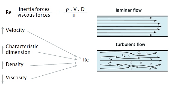
- The Reynolds number is one of the characteristic numbers used for predicting whether a flow condition will be laminar or turbulent. It is defined as the ratio of inertial forces to viscous forces.
 in which V is the mean flow velocity, D is a characteristic linear dimension, ρ fluid density, μ dynamic viscosity, and ν kinematic viscosity.
 - Laminar flow occurs at Re < 2000. Usually, a low-velocity flow is required, but this also depends on the size of an object.
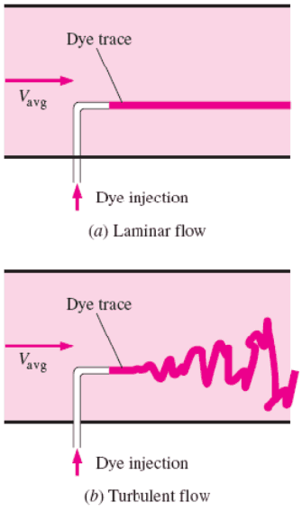
- For laminar flow, fluid particles move in straight lines. Layers of water flow over one another at different speeds with virtually no mixing between layers.
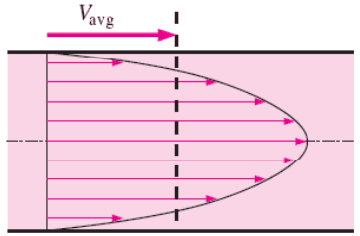
- The flow velocity profile for laminar flow in circular pipes is parabolic in shape, with a maximum flow at the center of the pipe and a minimum flow at the pipe walls. The average flow velocity is approximately one-half of the maximum velocity.
- Simple mathematical analysis is possible, but the laminar flow is rare in practice in water systems.
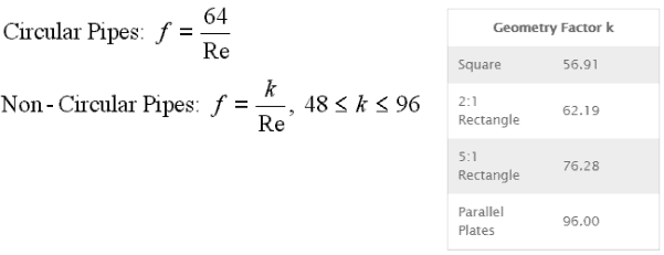
Darcy’s equation can be used to calculate major losses. The Darcy friction factor for laminar (slow) flows is a consequence of Poiseuille’s law that and it is given by the following equations:
In fluid dynamics, laminar flow is characterized by smooth or regular paths of fluid particles, in contrast to turbulent flow, which is characterized by the irregular movement of particles of the fluid. The fluid flows in parallel layers (with minimal lateral mixing), with no disruption between the layers. Therefore the laminar flow is also referred to as streamline or viscous flow.
The term streamline flow is descriptive of the flow because, in laminar flow, layers of water flow over one another at different speeds with virtually no mixing between layers. Fluid particles move in definite and observable paths or streamlines.
When a fluid is flowing through a closed channel such as a pipe or between two flat plates, either of two types of flow (laminar flow or turbulent flow) may occur depending on the velocity, viscosity of the fluid, and the size of the pipe. Laminar flow tends to occur at lower velocities and high viscosity. On the other hand, the turbulent flow tends to occur at higher velocities and low viscosity.
Since the laminar flow is common only in cases in which the flow
the channel is relatively small, the fluid is moving slowly, and its viscosity is relatively high. Laminar flow is not common in industrial processes. Most industrial flows, especially those in nuclear engineering, are turbulent. Nevertheless, laminar flow occurs at any Reynolds number near solid boundaries in a thin layer just adjacent to the surface. This layer is usually referred to as the laminar sublayer. It is very important in heat transfer.
Despite the small thickness of the laminar sublayer (usually much less than 1 percent of the pipe diameter), since it strongly influences the flow in the rest of the pipe. Any irregularity or roughness on the surface disturbs this layer and significantly affects the flow. Therefore, unlike laminar flow, the friction factor in turbulent flow is a strong function of surface roughness.
Reynolds Number
The Reynolds number is the ratio of inertial forces to viscous forces and is a convenient parameter for predicting if a flow condition will be laminar or turbulent. It can be interpreted that when the viscous forces are dominant (slow flow, low Re), they are sufficient enough to keep all the fluid particles in line, then the flow is laminar. Even very low Re indicates viscous creeping motion, where inertia effects are negligible. When the inertial forces dominate over the viscous forces (when the fluid flows faster and Re is larger), the flow is turbulent.
It is a dimensionless number
comprised of the physical characteristics of the flow. An increasing Reynolds number indicates increasing turbulence of flow.
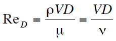
It is defined as:

where:
V is the flow velocity,
D is a characteristic linear dimension, (travelled length of the fluid; hydraulic diameter etc.)
ρ fluid density (kg/m3),
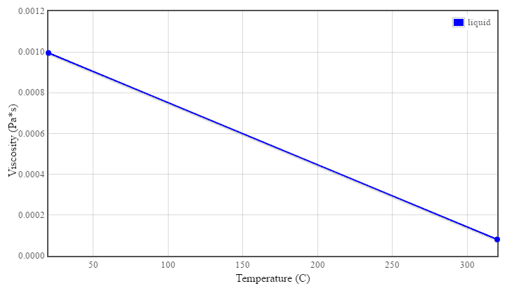
μ dynamic viscosity (Pa.s),
ν kinematic viscosity (m2/s); ν = μ / ρ.
All fluid flow is classified into one of two broad categories or regimes. These two flow regimes are:
- Single-phase Fluid Flow
- Multi-phase Fluid Flow (or Two-phase Fluid Flow)
This is a basic classification. All of the fluid flow equations (e.g.,, Bernoulli’s Equation) and relationships discussed in this section (Fluid Dynamics) were derived for the flow of a single phase of fluid, whether liquid or vapor. Solution of multi-phase fluid flow is very complex and difficult, and therefore it is usually in advanced courses of fluid dynamics.
 Another usually more common classification of flow regimes is according to the shape and type of streamlines. All fluid flow is classified into one of two broad categories. The fluid flow can be either laminar or turbulent, and therefore these two categories are:
- Laminar Flow
- Turbulent Flow
Laminar flow is characterized by smooth or regular paths of particles of the fluid. Therefore the laminar flow is also referred to as streamline or viscous flow. In contrast to laminar flow, turbulent flow is characterized by the irregular movement of particles of the fluid. The turbulent fluid does not flow in parallel layers, the lateral mixing is very high, and there is a disruption between the layers. Most industrial flows, especially those in nuclear engineering, are turbulent.
The flow regime can also be classified according to the geometry of a conduit or flow area. From this point of view, we distinguish:
- Internal Flow
- External Flow
Internal flow is a flow for which the fluid is confined by a surface. Detailed knowledge of the behavior of internal flow regimes is important in engineering because circular pipes can withstand high pressures and hence are used to convey liquids. On the other hand, external flow flows in which boundary layers develop freely, without constraints imposed by adjacent surfaces. Detailed knowledge of the behavior of external flow regimes is of importance, especially in aeronautics and aerodynamics.
Reynolds Number Regimes
Laminar flow. For practical purposes, if the Reynolds number is less than 2000, the flow is laminar. The accepted transition Reynolds number for flow in a circular pipe is Red,crit = 2300.
Transitional flow. At Reynolds numbers between about 2000 and 4000, the flow is unstable due to the onset of turbulence. These flows are sometimes referred to as transitional flows.
Turbulent flow. If the Reynolds number is greater than 3500, the flow is turbulent. Most fluid systems in nuclear facilities operate with turbulent flow.
It is an illustrative example, following data do not correspond to any reactor design.
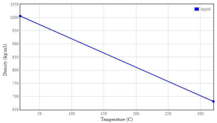
Pressurized water reactors are cooled and moderated by high-pressure liquid water (e.g.,, 16MPa). At this pressure, water boils at approximately 350°C (662°F). The inlet temperature of the water is about 290°C (⍴ ~ 720 kg/m3). The water (coolant) is heated in the reactor core to approximately 325°C (⍴ ~ 654 kg/m3) as the water flows through the core.
The primary circuit of typical PWRs is divided into 4 independent loops (piping diameter ~ 700mm). Each loop comprises a steam generator and one main coolant pump. Inside the reactor pressure vessel (RPV), the coolant first flows down outside the reactor core (through the downcomer). The flow is reversed up through the core from the bottom of the pressure vessel, where the coolant temperature increases as it passes through the fuel rods and the assemblies formed by them.
Assume:
- the primary piping flow velocity is constant and equal to 17 m/s,
- the core flow velocity is constant and equal to 5 m/s,
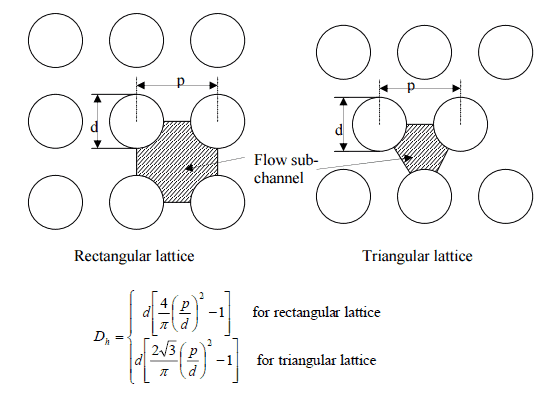
- the hydraulic diameter of the fuel channel, Dh, is equal to 2 cm
- the kinematic viscosity of the water at 290°C is equal to 0.12 x 10⁻⁶ m2/s
See also: Example: Flow rate through a reactor core
Determine
- the flow regime and the Reynolds number inside the fuel channel
- the flow regime and the Reynolds number inside the primary piping
The Reynolds number inside the primary piping is equal to:
ReD = 17 [m/s] x 0.7 [m] / 0.12×10⁻⁶ [m2/s] = 99 000 000
This fully satisfies the turbulent conditions.
The Reynolds number inside the fuel channel is equal to:
ReDH = 5 [m/s] x 0.02 [m] / 0.12×10⁻⁶ [m2/s] = 833 000
This also fully satisfies the turbulent conditions.
Pressure Loss Calculation
For laminar flow, the head loss is proportional to velocity rather than velocity squared. Thus the friction factor is inversely proportional to velocity.
The Darcy friction factor for laminar (slow) flows is a consequence of Poiseuille’s law that and it is given by the following equations:
Heat Transfer Coefficient
External Laminar Flow
The average Nusselt number over the entire plate is determined by:
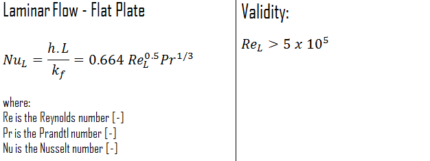
This relation gives the average heat transfer coefficient for the entire plate when the flow is laminar over the entire plate.
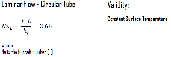
Internal Laminar Flow
Constant Surface Temperature
In laminar flow in a tube with constant surface temperature, both the friction factor and the heat transfer coefficient remain constant in the fully developed region.
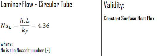
Constant Surface Heat Flux
Therefore, for fully developed laminar flow in a circular tube subjected to constant surface heat flux, the Nusselt number is a constant. There is no dependence on the Reynolds or the Prandtl numbers.