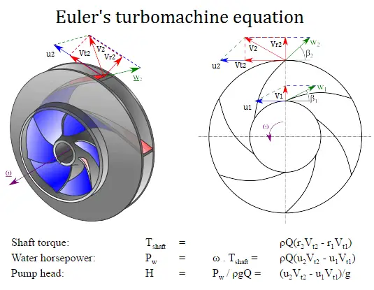
Euler’s turbomachine equations are:
Shaft torque: Tshaft = ρQ(r2Vt2 – r1Vt1)
Water horsepower: Pw = ω . Tshaft = ρQ(u2Vt2 – u1Vt1)
Pump head: H = Pw / ρgQ = (u2Vt2 – u1Vt1)/g
where
- r1 and r2 are the diameters of the impeller at the inlet and outlet, respectively.
- u1 and u2 are the absolute velocities of the impeller (u1 = r1 . ω) at the inlet and outlet, respectively.
- Vt1 and Vt2 are the tangential velocities of the flow at the inlet and outlet, respectively.
Euler’s turbomachine equations can predict the impact of changing the impeller geometry on the head. It does not matter when we deal with a pump or with a turbine. If torque and angular velocity are like a sign, work is being done on the fluid (a pump or compressor). If torque and angular velocity are of opposite sign, work is being extracted from the fluid (a turbine). Thus for the design aspect of turbines and pumps, the Euler equations are extremely useful.
Example: Pump Performance Calculation
 In this example, we will see how to predict
- the design discharge
- water horsepower
- the pump head
of a centrifugal pump. This performance data will be derived from Euler’s turbomachine equation:
Shaft torque: Tshaft = ρQ(r2Vt2 – r1Vt1)
Water horsepower: Pw = ω . Tshaft = ρQ(u2Vt2 – u1Vt1)
Pump head: H = Pw / ρgQ = (u2Vt2 – u1Vt1)/g
Given are the following data for a centrifugal water pump:
- diameters of the impeller at the inlet and outlet
- r1 = 10 cm
- r2 = 20 cm
- Speed = 1500 rpm (revolutions per minute)
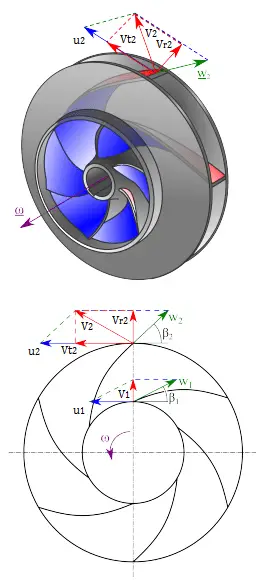
- the blade angle at inlet β1 = 30°
- the blade angle at outlet β2 = 20°
- assume that the blade widths at inlet and outlet are: b1 = b2 = 4 cm.
Solution:
First, we have to calculate the radial velocity of the flow at the outlet. From the velocity diagram, the radial velocity is equal to (we assume that the flow enters exactly normal to the impeller, so tangential component of velocity is zero):
Vr1 = u1 tan 30° = ω r1 tan 30° = 2π x (1500/60) x 0.1 x tan 30° = 9.1 m/s
The radial component of flow velocity determines how much the volume flow rate is entering the impeller. So when we know Vr1 at the inlet, we can determine the discharge of this pump according to the following equation. Here b1 means the blade width of the impeller at the inlet.
Q = 2π.r1.b1.Vr1 = 2π x 0.1 x 0.04 x 9.1 = 0.229 m3/s
In order to calculate the water horsepower (Pw) required, we have to determine the outlet tangential flow velocity Vt2, because it has been assumed that the inlet tangential velocity Vt1 is equal to zero.
The outlet radial flow velocity follows from conservation of Q:
Q = 2π.r2.b2.Vr2 ⇒ Vr2 = Q / 2π.r2.b2 = 0.229 / (2π x 0.2 x 0.04) = 4.56 m/s
From the figure (velocity triangle) outlet blade angle, β2, can be easily represented as follows.
cot β2 = (u2 – Vt2) / Vr2
and therefore the outlet tangential flow velocity Vt2 is:
Vt2 = u2 – Vr2 . cot 20° = ω r2 – Vr2 . cot 20° = 2π x 1500/60 x 0.2 – 4.56 x 2.75 = 31.4 – 12.5 = 18.9 m/s.
The water horsepower required is then:
Pw = ρ Q u2 Vt2 = 1000 [kg/m3] x 0.229 [m3/s] x 31.4 [m/s] x 18.9 [m/s] = 135900 W = 135.6 kW
and the pump head is:
H ≈ Pw / (ρ g Q) = 135900 / (1000 x 9.81 x 0.229) = 60.5 m