Although the theory of centrifugal pumps gives many qualitative results, the most important indicator of a pump’s performance lies in extensive hydraulic testing.
In industry, the characteristics of all pumps are usually read from their Q-H curve or performance curve (flow rate – height). As can be seen, the performance charts use a discharge – Q (usually in m3/h) and pump head – H (usually in m) as basic performance variables.
System Head
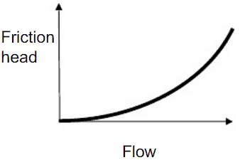 In the chapter on head loss, it was determined that both major losses and minor losses in piping systems are proportional to the square of the flow velocity. The system head loss must be directly proportional to the square of the volumetric flow rate because the volumetric flow rate is directly proportional to the flow velocity.
It must be added that the open hydraulic systems contain not only the friction head but also the elevation head, which must be considered. The elevation head (static head) represents the potential energy of a fluid due to its elevation above a reference level.
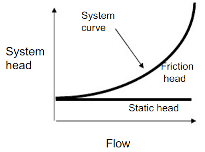 In many cases, the total head of a system is a combination of elevation head and friction head, as shown in the figure.
Most of the hydraulic systems are closed hydraulic loops in nuclear engineering, and these systems only have friction head (no static head).
Pump Head – Performance Curve
In fluid dynamics, the term pump head is used to measure the kinetic energy which a pump creates. Head is a measurement of the height of the incompressible fluid column the pump could create from the kinetic energy that the pump gives to the liquid. The head and flow rate determine the performance of a pump, which is graphically shown in the figure as the performance curve or pump characteristic curve. The main reason for using head instead of pressure to determine the performance of a centrifugal pump is that the height of the fluid column is not dependent on the specific gravity (weight) of the liquid. In contrast, the pressure from a pump will change. In terms of pressure, the pump head (ΔPpump) is the difference between system backpressure and the pump’s inlet pressure.
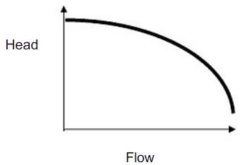 The maximum pump head of a centrifugal pump is mainly determined by the outside diameter of the pump’s impeller and the shaft angular velocity – speed of the rotating shaft. The head will also change as the volumetric flow rate through the pump is increased.
When a centrifugal pump is operating at a constant angular velocity, an increase in the system head (back pressure) on the flowing stream causes a reduction in the volumetric flow rate that the centrifugal pump can maintain.
The relationship between the pump head and the volumetric flow rate (Q) that a centrifugal pump can maintain is dependent on various physical characteristics of the pump as:
- the power supplied to the pump
- the angular velocity of the shaft
- the type and diameter of the impeller
and the used fluid:
- fluid density
- fluid viscosity
This relationship is very complicated, and its analysis lies in extensive hydraulic testing of certain centrifugal pumps, as seen in the picture below.
Operating Characteristics of a Hydraulic Loop
When we put together the frictional characteristics (system head) of a hydraulic loop and the performance curve, the result will describe the characteristics of the entire system (e.g.,, one loop of the primary circuit). The following figure shows a typical performance curve for a centrifugal pump related to the frictional system head.

On the vertical axis, the pump head is the difference between system backpressure and the pump’s inlet pressure (ΔPpump). On the horizontal axis, volumetric flow rate (Q ) is the fluid flow through the pump. As can be seen, the head is approximately constant at low discharge and then drops to zero at Qmax. At low discharge, the characteristics can be unstable (with a positive slope of the pump head). These are undesirable characteristics because an unstable pump may start to oscillate between the two possible combinations of flow rate, and the pipeline can vibrate.
At flow rate Q1, the pump gains more head than consumes the frictional losses. Therefore the flow rate through the system will increase. The flow rate will stabilize itself at the point where the frictional losses intersect the pump characteristics.
The following terms are defined to characterize the performance of centrifugal pumps:
- Shut-off Head
- Pump Efficiency
- Best Efficiency Point – BEP
- Brake Horsepower
- Net Positive Suction Head
Example: Pump Performance Calculation
 In this example, we will see how to predict
- the design discharge
- water horsepower
- the pump head
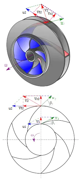
of a centrifugal pump. This performance data will be derived from the Euler’s turbomachine equation:
Shaft torque: Tshaft = ρQ(r2Vt2 – r1Vt1)
Water horsepower: Pw = ω . Tshaft = ρQ(u2Vt2 – u1Vt1)
Pump head: H = Pw / ρgQ = (u2Vt2 – u1Vt1)/g
Given are the following data for a centrifugal water pump:
- diameters of the impeller at the inlet and outlet
- r1 = 10 cm
- r2 = 20 cm
- Speed = 1500 rpm (revolutions per minute)
- the blade angle at inlet β1 = 30°
- the blade angle at outlet β2 = 20°
- assume that the blade widths at inlet and outlet are: b1 = b2 = 4 cm.
Solution:
First, we have to calculate the radial velocity of the flow at the outlet. From the velocity diagram, the radial velocity is equal to (we assume that the flow enters exactly normal to the impeller, so tangential component of velocity is zero):
Vr1 = u1 tan 30° = ω r1 tan 30° = 2π x (1500/60) x 0.1 x tan 30° = 9.1 m/s
The radial component of flow velocity determines how much the volume flow rate is entering the impeller. So when we know Vr1 at the inlet, we can determine the discharge of this pump according to the following equation. Here b1 means the blade width of the impeller at the inlet.
Q = 2π.r1.b1.Vr1 = 2π x 0.1 x 0.04 x 9.1 = 0.229 m3/s
In order to calculate the water horsepower (Pw) required, we have to determine the outlet tangential flow velocity Vt2, because it has been assumed that the inlet tangential velocity Vt1 is equal to zero.
The outlet radial flow velocity follows from conservation of Q:
Q = 2π.r2.b2.Vr2 ⇒ Vr2 = Q / 2π.r2.b2 = 0.229 / (2π x 0.2 x 0.04) = 4.56 m/s
From the figure (velocity triangle) outlet blade angle, β2, can be easily represented as follows.
cot β2 = (u2 – Vt2) / Vr2
and therefore the outlet tangential flow velocity Vt2 is:
Vt2 = u2 – Vr2 . cot 20° = ω r2 – Vr2 . cot 20° = 2π x 1500/60 x 0.2 – 4.56 x 2.75 = 31.4 – 12.5 = 18.9 m/s.
The water horsepower required is then:
Pw = ρ Q u2 Vt2 = 1000 [kg/m3] x 0.229 [m3/s] x 31.4 [m/s] x 18.9 [m/s] = 135900 W = 135.6 kW
and the pump head is:
H ≈ Pw / (ρ g Q) = 135900 / (1000 x 9.81 x 0.229) = 60.5 m
www.tvo.fi/uploads/julkaisut/tiedostot/ydinvoimalayks_OL3_ENG.pdf