Pump Head – Performance Curve
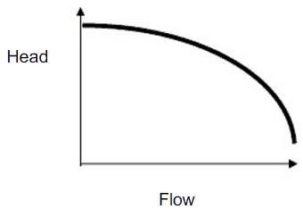
In fluid dynamics, the term pump head is used to measure the kinetic energy which a pump creates. Head is a measurement of the height of the incompressible fluid column the pump could create from the kinetic energy that the pump gives to the liquid. The head and flow rate determine the performance of a pump, which is graphically shown in the figure as the performance curve or pump characteristic curve. The main reason for using head instead of pressure to determine the performance of a centrifugal pump is that the height of the fluid column is not dependent on the specific gravity (weight) of the liquid. In contrast, the pressure from a pump will change. In terms of pressure, the pump head (ΔPpump) is the difference between system backpressure and the pump’s inlet pressure.
 The maximum pump head of a centrifugal pump is mainly determined by the outside diameter of the pump’s impeller and the shaft angular velocity – speed of the rotating shaft. The head will also change as the volumetric flow rate through the pump is increased.
When a centrifugal pump is operating at a constant angular velocity, an increase in the system head (back pressure) on the flowing stream causes a reduction in the volumetric flow rate that the centrifugal pump can maintain.
The relationship between the pump head and the volumetric flow rate (Q) that a centrifugal pump can maintain is dependent on various physical characteristics of the pump is:
- the power supplied to the pump
- the angular velocity of the shaft
- the type and diameter of the impeller
and the used fluid:
- fluid density
- fluid viscosity
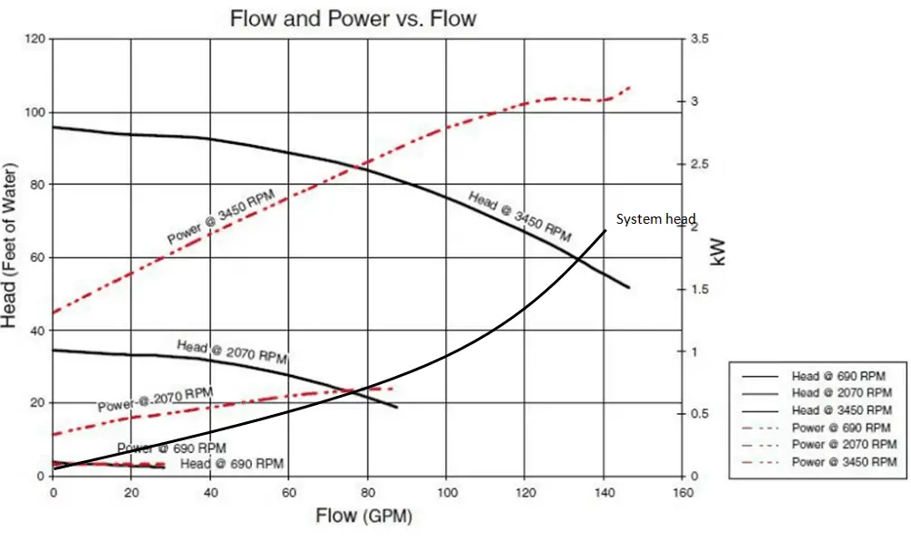
This relationship is very complicated, and its analysis lies in extensive hydraulic testing of certain centrifugal pumps, as seen in the picture below.
 In this example, we will see, how to predict
- the design discharge
- water horsepower
- the pump head
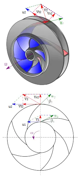
of a centrifugal pump. This performance data will be derived from the Euler’s turbomachine equation:
Shaft torque: Tshaft = ρQ(r2Vt2 – r1Vt1)
Water horsepower: Pw = ω . Tshaft = ρQ(u2Vt2 – u1Vt1)
Pump head: H = Pw / ρgQ = (u2Vt2 – u1Vt1)/g
Given are the following data for a centrifugal water pump:
- diameters of the impeller at the inlet and outlet
- r1 = 10 cm
- r2 = 20 cm
- Speed = 1500 rpm (revolutions per minute)
- the blade angle at inlet β1 = 30°
- the blade angle at outlet β2 = 20°
- assume that the blade widths at inlet and outlet are: b1 = b2 = 4 cm.
Solution:
First, we have to calculate the radial velocity of the flow at the outlet. From the velocity diagram, the radial velocity is equal to (we assume that the flow enters exactly normal to the impeller, so tangential component of velocity is zero):
Vr1 = u1 tan 30° = ω r1 tan 30° = 2π x (1500/60) x 0.1 x tan 30° = 9.1 m/s
The radial component of flow velocity determines how much the volume flow rate is entering the impeller. So when we know Vr1 at the inlet, we can determine the discharge of this pump according to the following equation. Here b1 means the blade width of the impeller at the inlet.
Q = 2π.r1.b1.Vr1 = 2π x 0.1 x 0.04 x 9.1 = 0.229 m3/s
In order to calculate the water horsepower (Pw) required, we have to determine the outlet tangential flow velocity Vt2, because it has been assumed that the inlet tangential velocity Vt1 is equal to zero.
The outlet radial flow velocity follows from conservation of Q:
Q = 2π.r2.b2.Vr2 ⇒ Vr2 = Q / 2π.r2.b2 = 0.229 / (2π x 0.2 x 0.04) = 4.56 m/s
From the figure (velocity triangle) outlet blade angle, β2, can be easily represented as follows.
cot β2 = (u2 – Vt2) / Vr2
and therefore the outlet tangential flow velocity Vt2 is:
Vt2 = u2 – Vr2 . cot 20° = ω r2 – Vr2 . cot 20° = 2π x 1500/60 x 0.2 – 4.56 x 2.75 = 31.4 – 12.5 = 18.9 m/s.
The water horsepower required is then:
Pw = ρ Q u2 Vt2 = 1000 [kg/m3] x 0.229 [m3/s] x 31.4 [m/s] x 18.9 [m/s] = 135900 W = 135.6 kW
and the pump head is:
H ≈ Pw / (ρ g Q) = 135900 / (1000 x 9.81 x 0.229) = 60.5 m
Series Operation of Centrifugal Pumps (Booster)
Centrifugal pumps are often used in parallel or series to increase the volumetric flow rate or compensate for large major or minor losses.
Series operation of centrifugal pumps is used to overcome large system head loss or gain large pressure increase when liquid is injected into a very high-pressure system (e.g.,, High-Pressure Safety Injection Systems in PWRs, where multi-stage pumps are used).
When a centrifugal pump is operated in a closed-loop, the resulting discharge pressure will be simply the sum of the suction pressure and the pressure normally developed by the pump when operating at zero suction pressure. Therefore it is well suited for use as a booster pump when operated in series. The head produced by two or more pumps is equal to the sum of the individual heads. The volumetric flow rate from the inlet of the first pump to the outlet of the second remains the same. In practical application, multi-stage pumps (multiple impeller pumps) are built to reach a higher pump head.
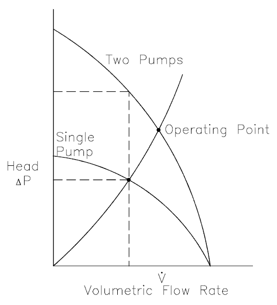
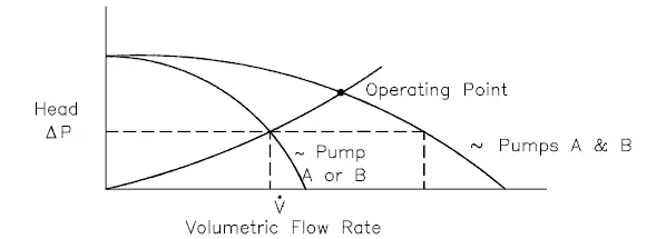
Parallel Operation of Centrifugal Pumps
Centrifugal pumps are often used in parallel or series to increase the volumetric flow rate in a system or compensate for large major or minor losses.
Parallel operation of centrifugal pumps is used to increase the flow rate through the system. Pumps operating in parallel take their suction from a common header and discharge into a common discharge. While head changes only slightly, flow is almost doubled at any given point. It must be noted the volumetric flow rate is less than twice the flow rate achieved by using a single pump. This is caused by a greater system head loss resulting from a higher flow rate.