For the internal flow regime, an entrance region is typical. In this region, a nearly inviscid upstream flow converges and enters the tube. The hydrodynamic entrance length is introduced to characterize this region and is approximately equal to:
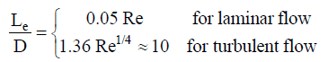
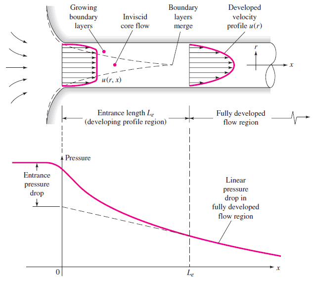
The maximum hydrodynamic entrance length, at ReD,crit = 2300 (laminar flow), is Le = 138d, where D is the diameter of the pipe. This is the longest development length possible. In turbulent flow, the boundary layers grow faster, and Le is relatively shorter. For any given problem, Le / D has to be checked to see if Le is negligible compared to the pipe length. The entrance effects may be neglected at a finite distance from the entrance because the boundary layers merge and the inviscid core disappears. The tube flow is then fully developed.
All fluid flow is classified into one of two broad categories or regimes. These two flow regimes are:
- Single-phase Fluid Flow
- Multi-phase Fluid Flow (or Two-phase Fluid Flow)
This is a basic classification. All of the fluid flow equations (e.g.,, Bernoulli’s Equation) and relationships discussed in this section (Fluid Dynamics) were derived to flow a single phase of fluid, whether liquid or vapor. Solution of multi-phase fluid flow is very complex and difficult, and therefore it is usually in advanced courses of fluid dynamics.
 Another usually more common classification of flow regimes is according to the shape and type of streamlines. All fluid flow is classified into one of two broad categories. The fluid flow can be either laminar or turbulent, and therefore these two categories are:
- Laminar Flow
- Turbulent Flow
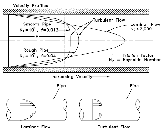
Laminar flow is characterized by smooth or in regular paths of particles of the fluid. Therefore the laminar flow is also referred to as streamline or viscous flow. In contrast to laminar flow, turbulent flow is characterized by the irregular movement of particles of the fluid. The turbulent fluid does not flow in parallel layers, the lateral mixing is very high, and there is a disruption between the layers. Most industrial flows, especially those in nuclear engineering, are turbulent.
The flow regime can also be classified according to the geometry of a conduit or flow area. From this point of view, we distinguish:
- Internal Flow
- External Flow
Internal flow is a flow for which a surface confines the fluid. Detailed knowledge of the behavior of internal flow regimes is important in engineering because circular pipes can withstand high pressures and hence are used to convey liquids. On the other hand, external flow flows in which boundary layers develop freely, without constraints imposed by adjacent surfaces. Detailed knowledge of the behavior of external flow regimes is of importance, especially in aeronautics and aerodynamics.
Hydraulic Diameter
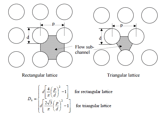
To further simplify calculations and enlarge the range of applications, the hydraulic diameter is introduced:

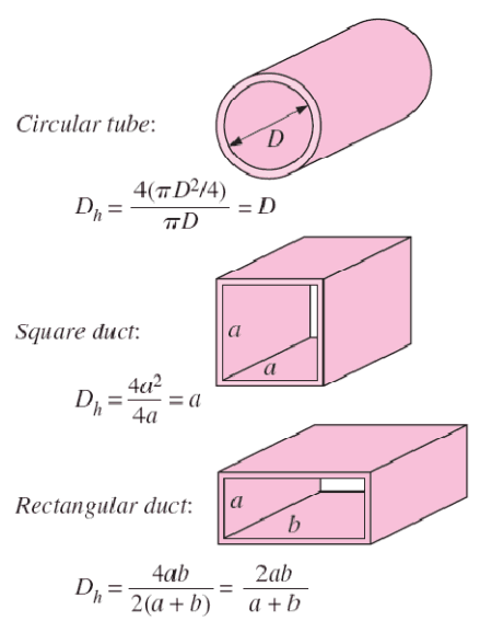 The hydraulic diameter, Dh, is a commonly used term when handling flow in non-circular tubes and channels. The hydraulic diameter transforms non-circular ducts into pipes of equivalent diameter. Using this term, one can calculate many things in the same way as for a round tube. In this equation, A is the cross-sectional area, and P is the wetted perimeter of the cross-section.
Most industrial flows, especially those in nuclear engineering, are turbulent. For single straight pipe analysis, assuming unidirectional flow, geometric and kinematic pipe-design problems rely on the Moody chart and can be grouped as follows:
- Evaluate the necessary pump characteristics (Q-H characteristics) based on the computed pressure drop Δp to convey a given maximum flow rate.
- Calculate a specified pressure drop for the pipe of diameter D, of given pipe length and flow rate. This problem requires an iterative procedure because the Reynolds number, and hence the friction factor f, is not known.
- Calculate the flow rate Q for a given pipe geometry (D, L, ε/D) and pressure drop, where ε/D is the relative surface roughness. This problem requires an iterative procedure because the Reynolds number, and hence the friction factor f, is not known.
See also: Power-law velocity profile
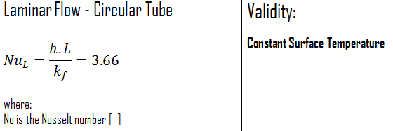
In laminar flow in a tube with constant surface temperature, both the friction factor and the heat transfer coefficient remain constant in the fully developed region.
Constant Surface Heat Flux
Therefore, for fully developed laminar flow in a circular tube subjected to constant surface heat flux, the Nusselt number is a constant. There is no dependence on the Reynolds or the Prandtl numbers.

For fully developed (hydrodynamically and thermally) turbulent flow in a smooth circular tube, the local Nusselt number may be obtained from the well-known Dittus-Boelter equation. The DittusBoelter equation is easy to solve. Still, it is less accurate when there is a large temperature difference across the fluid and is less accurate for rough tubes (many commercial applications) since it is tailored to smooth tubes.
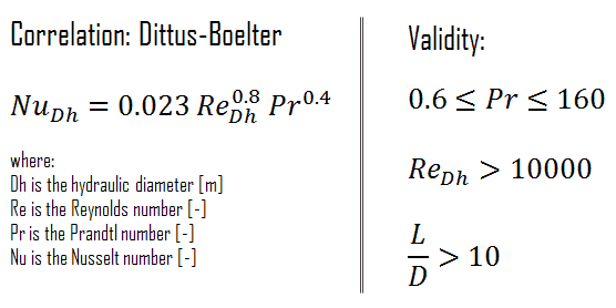
The Dittus-Boelter correlation may be used for small to moderate temperature differences, Twall – Tavg, with all properties evaluated at an, averaged temperature Tavg.
For flows characterized by large property variations, the corrections (e.g.,, a viscosity correction factor μ/μwall) must be considered, for example, as Sieder and Tate recommend.
Example: Reynolds number for primary piping and a fuel bundle
It is an illustrative example, following data do not correspond to any reactor design.
Pressurized water reactors are cooled and moderated by high-pressure liquid water (e.g.,, 16MPa). At this pressure, water boils at approximately 350°C (662°F). The inlet temperature of the water is about 290°C (⍴ ~ 720 kg/m3). The water (coolant) is heated in the reactor core to approximately 325°C (⍴ ~ 654 kg/m3) as the water flows through the core.
The primary circuit of typical PWRs is divided into 4 independent loops (piping diameter ~ 700mm). Each loop comprises a steam generator and one main coolant pump. Inside the reactor pressure vessel (RPV), the coolant first flows down outside the reactor core (through the downcomer). The flow is reversed up through the core from the bottom of the pressure vessel, where the coolant temperature increases as it passes through the fuel rods and the assemblies formed by them.
Assume:
- the primary piping flow velocity is constant and equal to 17 m/s,
- the core flow velocity is constant and equal to 5 m/s,
- the hydraulic diameter of the fuel channel, Dh, is equal to 2 cm
- the kinematic viscosity of the water at 290°C is equal to 0.12 x 10⁻⁶ m2/s
See also: Example: Flow rate through a reactor core
Determine
- the flow regime and the Reynolds number inside the fuel channel
- the flow regime and the Reynolds number inside the primary piping
The Reynolds number inside the primary piping is equal to:
ReD = 17 [m/s] x 0.7 [m] / 0.12×10⁻⁶ [m2/s] = 99 000 000
This fully satisfies the turbulent conditions.
The Reynolds number inside the fuel channel is equal to:
ReDH = 5 [m/s] x 0.02 [m] / 0.12×10⁻⁶ [m2/s] = 833 000
This also fully satisfies the turbulent conditions.