
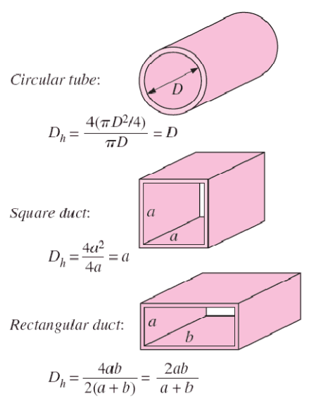
 The hydraulic diameter, Dh, is a commonly used term when handling flow in non-circular tubes and channels. The hydraulic diameter transforms non-circular ducts into pipes of equivalent diameter. Using this term, one can calculate many things in the same way as for a round tube. In this equation A is the cross-sectional area, and P is the wetted perimeter of the cross-section.
Example: Reynolds number for primary piping and a fuel bundle
It is an illustrative example, following data do not correspond to any reactor design.
Pressurized water reactors are cooled and moderated by high-pressure liquid water (e.g.,, 16MPa). At this pressure, water boils at approximately 350°C (662°F). The inlet temperature of the water is about 290°C (⍴ ~ 720 kg/m3). The water (coolant) is heated in the reactor core to approximately 325°C (⍴ ~ 654 kg/m3) as the water flows through the core.
The primary circuit of typical PWRs is divided into 4 independent loops (piping diameter ~ 700mm). Each loop comprises a steam generator and one main coolant pump. Inside the reactor pressure vessel (RPV), the coolant first flows down outside the reactor core (through the downcomer). The flow is reversed up through the core from the bottom of the pressure vessel, where the coolant temperature increases as it passes through the fuel rods and the assemblies formed by them.
Assume:
- the primary piping flow velocity is constant and equal to 17 m/s,
- the core flow velocity is constant and equal to 5 m/s,
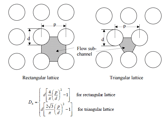
- the hydraulic diameter of the fuel channel, Dh, is equal to 1 cm
- the kinematic viscosity of the water at 290°C is equal to 0.12 x 10⁻⁶ m2/s
See also: Example: Flow rate through a reactor core
Determine
- the flow regime and the Reynolds number inside the fuel channel
- the flow regime and the Reynolds number inside the primary piping
The Reynolds number inside the primary piping is equal to:
ReD = 17 [m/s] x 0.7 [m] / 0.12×10⁻⁶ [m2/s] = 99 000 000
This fully satisfies the turbulent conditions.
The Reynolds number inside the fuel channel is equal to:
ReDH = 5 [m/s] x 0.01 [m] / 0.12×10⁻⁶ [m2/s] = 416 600
This also fully satisfies the turbulent conditions.