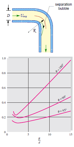
The flow-through elbows are quite complicated. Any curved pipe always induces a larger loss than the simple straight pipe. This is because, in a curved pipe, the flow separates on the curved walls. For a very small radius of curvature, the incoming flow is unable to make the turn at the bend. Therefore the flow separates and in part stagnates against the opposite side of the pipe. In this part of the bend, the pressure raises (as a result of Bernoulli’s principle), and the velocity decreases.
An interesting feature of the K-values for elbows is their non-monotone behavior as the R/D ratio increases. The K-values include both the local losses and frictional losses of the pipe. The local losses, caused by flow separation and secondary flow, decrease with R/D, while the frictional losses increase because the bend length increases. Therefore there is a minimum in the K-value near the normalized radius of curvature of 3.
Summary:
- Head loss of the hydraulic system is divided into two main categories:
- Major Head Loss – due to friction in straight pipes
- Minor Head Loss – due to components as valves, bends…
- A special form of Darcy’s equation can be used to calculate minor losses.
- The minor losses are roughly proportional to the square of the flow rate, and therefore they can be easily integrated into the Darcy-Weisbach equation through resistance coefficient K.
- As a local pressure loss, fluid acceleration in a heated channel can also be considered.
There are the following methods:
- Equivalent length method
- K-method (resistance coeff. method)
- 2K-method
- 3K-method
Why is head loss very important?
As can be seen from the picture, the head loss is formed key characteristic of any hydraulic system. In systems in which some certain flowrate must be maintained (e.g.,, to provide sufficient cooling or heat transfer from a reactor core), the equilibrium of the head loss and the head added by a pump determine the flow rate through the system.
