Drag is generally caused by two phenomena:
-
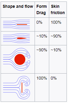
Source: wikipedia.org License: CC BY-SA 3.0 Skin Friction. In general, when a fluid flows over a stationary surface, e.g., the flat plate, the bed of a river, or the pipe wall, the fluid touching the surface is brought to rest by the shear stress at the wall. The boundary layer is the region in which flow adjusts from zero velocity at the wall to a maximum in the mainstream of the flow. Therefore, a moving fluid exerts tangential shear forces on the surface because of the no-slip condition caused by viscous effects. This type of drag force depends especially on the geometry, the roughness of the solid surface, and the type of fluid flow.
- Form Drag. Form drag, also known as pressure drag, arises because of the shape and size of the object. This type of drag force is an interesting consequence the Bernoulli’s effect. According to Bernoulli’s principle, faster-moving air exerts less pressure, and this causes that there can be a pressure difference between surfaces of the object. The general size and shape of the body are the most important factors in form drag. Generally, bodies with a larger presented geometric cross-section will have higher drag than thinner bodies.

Both of these forces, in general, have components in the direction of flow, and thus the resulting drag force is due to the combined effects of pressure and skin friction forces in the flow direction.
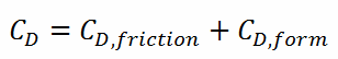
When the friction and pressure drag coefficients are available, the total drag coefficient is determined by simply adding them:
Most drag is due to friction drag at low Reynolds numbers, and this is especially the case for highly streamlined bodies such as airfoils. On the other hand, the pressure drop is significant at a high Reynolds number, which increases form drag.
The components of the pressure and skin friction forces in the normal direction to flow tend to move the body in that direction, and their sum is called lift.
The lift is an upward-acting force on an aircraft wing or airfoil in aeronautics. Bernoulli’s principle requires airfoil to be of an asymmetrical shape.
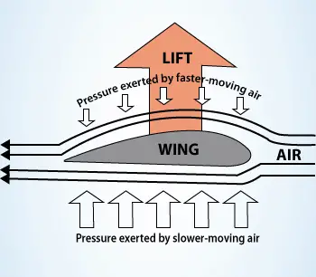 The lift is an upward-acting force on an aircraft wing or airfoil in aeronautics. Bernoulli’s principle requires airfoil to be of an asymmetrical shape, and its surface area must be greater on the top than on the bottom. As the air flows over the airfoil, it is displaced more by the top surface than the bottom. According to the continuity principle, this displacement must lead to an increase in flow velocity (resulting in a decrease in pressure). The flow velocity is increased by the bottom airfoil surface but considerably less than the flow on the top surface. The lift force of an airfoil, characterized by the lift coefficient, can be changed during the flight by changes in the shape of an airfoil. The lift coefficient can thus be even doubled with relatively simple devices (flaps and slats) if used on the full span of the wing.
The use of Bernoulli’s principle may not be correct. Bernoulli’s principle assumes incompressibility of the air, but in reality, the air is easily compressible. But there are more limitations of explanations based on Bernoulli’s principle. There are two main popular explanations of lift:
- Explanation based on downward deflection of the flow – Newton’s third law
- Explanation based on changes in flow speed and pressure – Continuity principle and Bernoulli’s principle
Both explanations correctly identify some aspects of the lift forces but leave other important aspects of the phenomenon unexplained. A more comprehensive explanation involves both changes in flow speed and downward deflection and requires looking at the flow in more detail.
See more: Doug McLean, Understanding Aerodynamics: Arguing from the Real Physics. John Wiley & Sons Ltd. 2013. ISBN: 978-1119967514
Skin Friction – Friction Drag
As was written, when a fluid flows over a stationary surface, e.g., the flat plate, the bed of a river, or the pipe wall, the fluid touching the surface is brought to rest by the shear stress at the wall. The boundary layer is the region in which flow adjusts from zero velocity at the wall to a maximum in the mainstream of the flow. Therefore, a moving fluid exerts tangential shear forces on the surface because of the no-slip condition caused by viscous effects. This type of drag force depends especially on the geometry, the roughness of the solid surface (only in turbulent flow), and the type of fluid flow. The friction drag is proportional to the surface area. Therefore, bodies with a larger surface area will experience a larger friction drag. This is why commercial airplanes reduce their total surface area to save fuel. Friction drag is a strong function of viscosity, and an “idealized” fluid with zero viscosity would produce zero friction drag since the wall shear stress would be zero.
Skin friction is caused by viscous drag in the boundary layer around the object. Basic characteristics of all laminar and turbulent boundary layers are shown in the developing flow over a flat plate. The stages of the formation of the boundary layer are shown in the figure below:
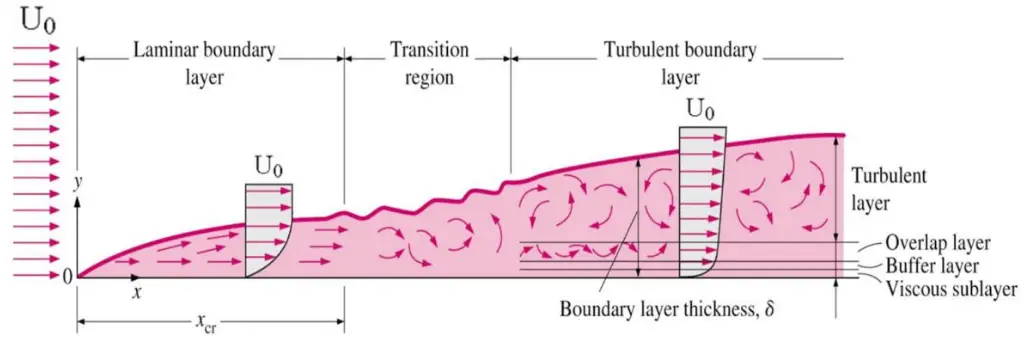
Boundary layers may be either laminar or turbulent, depending on the value of the Reynolds number.
The boundary layer is laminar for lower Reynolds numbers, and the streamwise velocity changes uniformly as one moves away from the wall, as shown on the left side of the figure. As the Reynolds number increases (with x), the flow becomes unstable. Finally, the boundary layer is turbulent for higher Reynolds numbers, and the streamwise velocity is characterized by unsteady (changing with time) swirling flows inside the boundary layer.
The transition from laminar to turbulent boundary layer occurs when Reynolds number at x exceeds Rex ~ 500,000. The transition may occur earlier, but it is dependent especially on the surface roughness. The turbulent boundary layer thickens more rapidly than the laminar boundary layer due to increased shear stress at the body surface.
There are two ways to decrease friction drag:
- the first is to shape the moving body so that laminar flow is possible
- the second method is to increase the length and decrease the cross-section of the moving object as much as practicable.
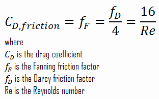
The skin friction coefficient, CD,friction, is defined by

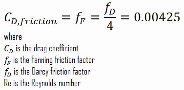
It must be noted the skin friction coefficient is equal to the Fanning friction factor. The Fanning friction factor, named after John Thomas Fanning, is a dimensionless number that is one-fourth of the Darcy friction factor. As can be seen, there is a connection between skin friction forces and frictional head losses.
See also: Darcy Friction Factor
For laminar flow in a pipe, the Fanning friction factor (skin friction coefficient) is a consequence of Poiseuille’s law that and it is given by the following equations:
However, things are more difficult in turbulent flows, as the friction factor depends strongly on the pipe roughness. The friction factor for fluid flow can be determined using a Moody chart. For example:

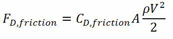
The frictional component of the drag force is given by:
Form Drag – Pressure Drag
 Form drag, also known as pressure drag, arises because of the shape and size of the object. The pressure drag is proportional to the difference between the pressures acting on the front and back of the immersed body and the frontal area. This type of drag force is also an interesting consequence the Bernoulli’s effect. According to Bernoulli’s principle, faster-moving air exerts less pressure, and this causes that there can be a pressure difference between surfaces of the object. The general size and shape of the body are the most important factors in form drag. Generally, bodies with a larger presented geometric cross-section will have higher drag than thinner bodies.
As can be seen from the figure, the drag force arises from the difference between the pressures acting on the front and back of the immersed body. For this force can be calculated (for this case) simply using the definition of pressure as:

Since the head loss is roughly proportional to the square of the flow rate in most engineering flows, the total drag coefficient can be determined by simply adding the friction and pressure drag coefficients:
Drag Force – Drag Equation
The drag force, FD, depends on the density of the fluid, the upstream velocity, and the size, shape, and orientation of the body, among other things. One way to express this is by using the drag equation. The drag equation is a formula used to calculate the drag force experienced by an object due to movement through a fluid.
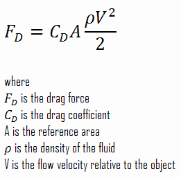
The reference area, A, is defined as the area of the orthographic projection of the object on a plane perpendicular to the direction of motion. For hollow objects, the reference area may be significantly larger than the cross-sectional area, but for non-hollow objects, it is the same as a cross-sectional area.
Drag Coefficient – Drag Characteristics
As was written, the drag characteristics of a body are represented by the dimensionless drag coefficient, CD, defined as:
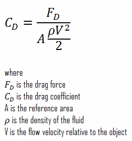
The reference area, A, is defined as the area of the orthographic projection of the object on a plane perpendicular to the direction of motion. For hollow objects, the reference area may be significantly larger than the cross-sectional area, but for non-hollow objects, it is the same as a cross-sectional area. As can be seen, the drag coefficient is primarily a function of the shape of the body and takes into account both skin friction and form drag. It may also depend on the Reynolds number and the surface roughness.
When the friction and pressure drag coefficients are available, the total drag coefficient is determined by simply adding them:
Most drag is due to friction drag at low Reynolds numbers, and this is especially the case for highly streamlined bodies such as airfoils. On the other hand, the pressure drop is significant at a high Reynolds number, which increases form drag.
Drag Force in Nuclear Engineering
Analysis of the hydraulic lift force is one of the most important analyses in designing a fuel assembly and analyzing the hydraulic compatibility of mixed cores. The vertical forces are induced by upward high-velocity flow through the reactor core, and the flow path for the reactor coolant through the reactor vessel would be:
-

Example of flow rates in a reactor. It is an illustrative example, and the data do not represent any reactor design. The coolant enters the reactor vessel at the inlet nozzle and hits against the core barrel.
- The core barrel forces the water to flow downward in the space between the reactor vessel wall and the core barrel. This space is usually known as the downcomer.
- The flow is reversed up through the core from the bottom of the pressure vessel to pass through the fuel assemblies, where the coolant temperature increases as it passes through the fuel rods.
- Finally, the hotter reactor coolant enters the upper internals region, where it is routed out the outlet nozzle into the hot legs of the primary circuit and goes on to the steam generators.

Fuel assemblies are held by the upper guide structure assembly, which defines the top of the core. This assembly is made of stainless steel and has many purposes. The upper guide structure assembly exerts an axial force on fuel assemblies (through springs in the top nozzle), thus defining the exact position of the fuel assembly in the core. The upper guide structure assembly flange is held in place and preloaded by the RPV closure head flange. The upper guide structure assembly also guides and protects control rod assemblies and in-core instrumentation.
Required downforce of the upper guide structure assembly on fuel assemblies must be carefully calculated. Insufficient downforce can result in the lift of the fuel assembly. On the other hand, an excessive downforce can result in bowing of fuel assembly, which is also unacceptable.
Example: Drag Force – Drag Coefficient – Fuel Bundle
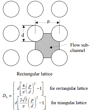 Calculate the friction drag of a single fuel rod inside a reactor core at normal operation (design flow rate). Assume that this fuel rod is part of a fuel bundle with the rectangular fuel lattice, and this fuel bundle does not contain spacing grids. Its height is h = 4m, and the core flow velocity is constant and equal to Vcore = 5 m/s.
Assume that:
- the outer diameter of the cladding is: d = 2 x rZr,1 = 9,3 mm
- the pitch of fuel pins is: p = 13 mm
- the relative roughness is ε/D = 5×10⁻⁴
- the fluid density is: ρ = 714 kg/m3
- the core flow velocity is constant and equal to Vcore = 5 m/s
- the average temperature of reactor coolant is: Tbulk = 296°C
Calculation of the Reynolds number
To calculate the Reynolds number, we have to know:
- the outer diameter of the cladding is: d = 2 x rZr,1 = 9,3 mm (to calculate the hydraulic diameter)
- the pitch of fuel pins is: p = 13 mm (to calculate the hydraulic diameter)
- the dynamic viscosity of saturated water at 300°C is: μ = 0.0000859 N.s/m2
- the fluid density is: ρ = 714 kg/m3
The hydraulic diameter, Dh, is a commonly used term when handling flow in non-circular tubes and channels. The hydraulic diameter of the fuel channel, Dh, is equal to 13,85 mm.
See also: Hydraulic Diameter
The Reynolds number inside the fuel channel is then equal to:
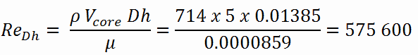
This fully satisfies the turbulent conditions.
Calculation of the Skin Friction Coefficient
The friction factor for turbulent flow depends strongly on the relative roughness. It is determined by the Colebrook equation or can be determined using the Moody chart. The Moody chart for Re = 575 600 and ε/D = 5 x 10⁻⁴ returns following values:
- the Darcy friction factor is equal to fD = 0.017
- the Fanning friction factor is equal to fF = fD/4 = 0.00425
Therefore the skin friction coefficient is equal to:
Calculation of the Drag Force
To calculate the drag force, we have to know:
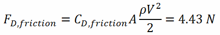
- the skin friction coefficient, which is: CD,friction = 0.00425
- the area of pin surface, which is: A = π.d.h = 0.1169 m2
- the fluid density, which is: ρ = 714 kg/m3
- the core flow velocity, which is constant and equal to Vcore = 5 m/s
From the skin friction coefficient, which is equal to the Fanning friction factor, we can calculate the frictional component of the drag force. The drag force is given by:
Assuming that a fuel assembly can have, for example, 289 fuel pins (17×17 fuel assembly), the frictional component of the drag force is then of the order of kilonewtons. Moreover, this drag force originates purely from the skin friction on the fuel bundle. But typical PWR fuel assembly contains other components which influence the fuel assembly hydraulics:
- Fuel rods. Fuel rods contain fuel and burnable poisons.
- Top nozzle. Provides the mechanical support for the fuel assembly structure.
- Bottom nozzle. Provides the mechanical support for the fuel assembly structure.
- Spacing grid. Ensures an exact guiding of the fuel rods.
- Guide thimble tube. Vacant tube for control rods or in-core instrumentation.
As was written, the second component of the drag force is the form drag. Form drag, also known as pressure drag, arises because of the shape and size of the object. The pressure drag is proportional to the difference between the pressures acting on the front and back of the immersed body and the frontal area.
Pressure Drop – Fuel Assembly
In general, total fuel assembly pressure drop is formed by fuel bundle frictional drop (dependent on relative roughness of fuel rods, Reynolds number, hydraulic diameter, etc.) and other pressure drops of structural elements (top and bottom nozzle, spacing grids, or mixing grids).
In general, it is not so simple to calculate pressure drops in fuel assemblies (especially the spacing grids), and it belongs to the key know-how of certain fuel manufacturers. Mostly, pressure drops are measured in experimental hydraulic loops rather than calculated.
Engineers use the pressure loss coefficient, PLC. It is noted K or ξ (pronounced “xi”). This coefficient characterizes pressure loss of a certain hydraulic system or a part of a hydraulic system, and it can be easily measured in hydraulic loops. The pressure loss coefficient can be defined or measured for both straight pipes and especially for local (minor) losses.
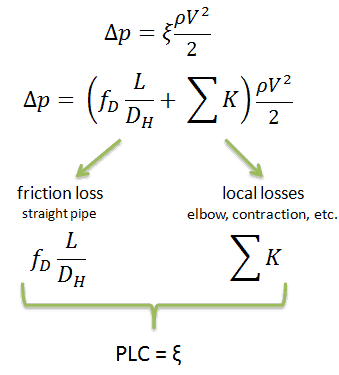
Using data from the example mentioned above, the pressure loss coefficient (only frictional from the straight pipe) is equal to ξ = fDL/DH = 4.9. But the overall pressure loss coefficient (including spacing grids, top, and bottom nozzles, etc.) is usually about three times higher. This PLC (ξ = 4.9) causes the pressure drop to be of the order of (using the previous inputs) Δpfriction = 4.9 x 714 x 52/ 2 = 43.7 kPa (without spacing grids, top, and bottom nozzles). About three times higher real PLC means about three times higher Δpfuel will be.
The overall reactor pressure loss, Δpreactor, must include:
- downcomer and reactor bottom
- lower support plate
- fuel assembly including spacing grids, top and bottom nozzles, and other structural components – Δpfuel
- upper guide structure assembly
As a result, the overall reactor pressure loss – Δpreactor is usually of the order of hundreds kPa (let say 300 – 400 kPa) for design parameters.