The reference area, A, is defined as the area of the orthographic projection of the object on a plane perpendicular to the direction of motion. For hollow objects, the reference area may be significantly larger than the cross-sectional area, but for non-hollow objects, it is the same as a cross-sectional area. As can be seen, the drag coefficient is primarily a function of the shape of the body and takes into account both skin friction and form drag. It may also depend on the Reynolds number and the surface roughness.
When the friction and pressure drag coefficients are available, the total drag coefficient is determined by simply adding them:
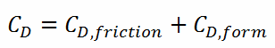
Most drag is due to friction drag at low Reynolds numbers, and this is especially the case for highly streamlined bodies such as airfoils. On the other hand, the pressure drop is significant at a high Reynolds number, which increases form drag.
Drag Force – Drag Equation
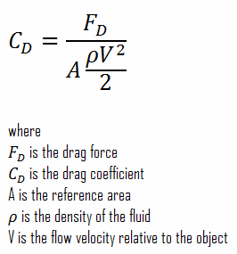
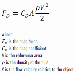
The drag force, FD, depends on the density of the fluid, the upstream velocity, and the size, shape, and orientation of the body, among other things. One way to express this is by using the drag equation. The drag equation is a formula used to calculate the drag force experienced by an object due to movement through a fluid.
The reference area, A, is defined as the area of the orthographic projection of the object on a plane perpendicular to the direction of motion. For hollow objects, the reference area may be significantly larger than the cross-sectional area, but for non-hollow objects, it is the same as a cross-sectional area.
Calculation of the Skin Friction Coefficient
The friction factor for turbulent flow depends strongly on the relative roughness. It is determined by the Colebrook equation or can be determined using the Moody chart. The Moody chart for Re = 575 600 and ε/D = 5 x 10⁻⁴ returns following values:
- the Darcy friction factor is equal to fD = 0.017
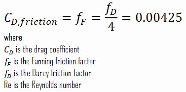
- the Fanning friction factor is equal to fF = fD/4 = 0.00425
Therefore the skin friction coefficient is equal to:
Calculation of the Drag Force
To calculate the drag force, we have to know:
- the skin friction coefficient, which is: CD,friction = 0.00425
- the area of pin surface, which is: A = π.d.h = 0.1169 m2
- the fluid density, which is: ρ = 714 kg/m3
- the core flow velocity, which is constant and equal to Vcore = 5 m/s
From the skin friction coefficient, which is equal to the Fanning friction factor, we can calculate the frictional component of the drag force. The drag force is given by:
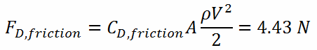
Assuming that a fuel assembly can have, for example, 289 fuel pins (17×17 fuel assembly), the frictional component of the drag force is then of the order of kilonewtons. Moreover, this drag force originates purely from the skin friction on the fuel bundle. But typical PWR fuel assembly contains other components which influence the fuel assembly hydraulics:
- Fuel rods. Fuel rods contain fuel and burnable poisons.
- Top nozzle. Provides the mechanical support for the fuel assembly structure.
- Bottom nozzle. Provides the mechanical support for the fuel assembly structure.
- Spacing grid. Ensures an exact guiding of the fuel rods.
- Guide thimble tube. Vacant tube for control rods or in-core instrumentation.
As was written, the second component of the drag force is the form drag. Form drag, also known as pressure drag, arises because of the shape and size of the object. The pressure drag is proportional to the difference between the pressures acting on the front and back of the immersed body and the frontal area.