The drag equation is a formula used to calculate the drag force experienced by an object due to movement through a fluid.
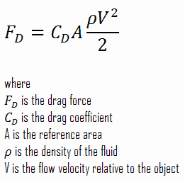
The reference area, A, is defined as the area of the orthographic projection of the object on a plane perpendicular to the direction of motion. For hollow objects, the reference area may be significantly larger than the cross-sectional area, but for non-hollow objects, it is the same as a cross-sectional area.
What is Drag in Physics
In fluid dynamics, drag is a force acting opposite to the relative motion of any moving object. The force a flowing fluid exerts on a body in the flow direction. Unlike other resistive forces, such as dry friction, nearly independent of velocity, drag forces depend on velocity. Drag force is proportional to the velocity for a laminar flow and the squared velocity for a turbulent flow. Drag is generally caused by two phenomena:
-
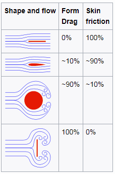
Source: wikipedia.org License: CC BY-SA 3.0 Skin Friction. In general, when a fluid flows over a stationary surface, e.g., the flat plate, the bed of a river, or the pipe wall, the fluid touching the surface is brought to rest by the shear stress at the wall. The boundary layer is the region in which flow adjusts from zero velocity at the wall to a maximum in the mainstream of the flow. Therefore, a moving fluid exerts tangential shear forces on the surface because of the no-slip condition caused by viscous effects. This type of drag force depends especially on the geometry, the roughness of the solid surface, and the type of fluid flow.
- Form Drag. Form drag, also known as pressure drag, arises because of the shape and size of the object. This type of drag force is an interesting consequence the Bernoulli’s effect. According to Bernoulli’s principle, faster-moving air exerts less pressure, and this causes that there can be a pressure difference between surfaces of the object. The general size and shape of the body are the most important factors in form drag. Generally, bodies with a larger presented geometric cross-section will have higher drag than thinner bodies.

Both of these forces, in general, have components in the direction of flow, and thus the resulting drag force is due to the combined effects of pressure and skin friction forces in the flow direction.
When the friction and pressure drag coefficients are available, the total drag coefficient is determined by simply adding them:
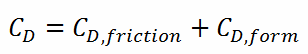
Most drag is due to friction drag at low Reynolds numbers, especially for highly streamlined bodies such as airfoils. On the other hand, the pressure drop is significant at a high Reynolds number, which increases form drag.
The components of the pressure and skin friction forces in the normal direction to flow tend to move the body in that direction, and their sum is called lift.
The lift is an upward-acting force on an aircraft wing or airfoil in aeronautics. Bernoulli’s principle requires airfoil to be of an asymmetrical shape.
Drag Force in Nuclear Engineering
Analysis of the hydraulic lift force is one of the most important analyses in designing a fuel assembly and analyzing the hydraulic compatibility of mixed cores. The vertical forces are induced by upward high-velocity flow through the reactor core, and the flow path for the reactor coolant through the reactor vessel would be:
-

Example of flow rates in a reactor. It is an illustrative example, and the data do not represent any reactor design. The coolant enters the reactor vessel at the inlet nozzle and hits against the core barrel.
- The core barrel forces the water to flow downward in the space between the reactor vessel wall and the core barrel. This space is usually known as the downcomer.
- The flow is reversed up through the core from the bottom of the pressure vessel to pass through the fuel assemblies, where the coolant temperature increases as it passes through the fuel rods.
- Finally, the hotter reactor coolant enters the upper internals region, where it is routed out the outlet nozzle into the hot legs of the primary circuit and goes on to the steam generators.

Fuel assemblies are held by the upper guide structure assembly, which defines the top of the core. This assembly is made of stainless steel and has many purposes. The upper guide structure assembly exerts an axial force on fuel assemblies (through springs in the top nozzle), thus defining the exact position of the fuel assembly in the core. The upper guide structure assembly flange is held in place and preloaded by the RPV closure head flange. The upper guide structure assembly also guides and protects control rod assemblies and in-core instrumentation.
Required downforce of the upper guide structure assembly on fuel assemblies must be carefully calculated. Insufficient downforce can result in the lift of the fuel assembly. On the other hand, an excessive downforce can result in bowing of fuel assembly, which is also unacceptable.
Example: Drag Force – Drag Coefficient – Fuel Bundle
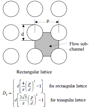 Calculate the friction drag of a single fuel rod inside a reactor core at normal operation (design flow rate). Assume that this fuel rod is part of a fuel bundle with the rectangular fuel lattice, and this fuel bundle does not contain spacing grids. Its height is h = 4m, and the core flow velocity is constant and equal to Vcore = 5 m/s.
Assume that:
- the outer diameter of the cladding is: d = 2 x rZr,1 = 9,3 mm
- the pitch of fuel pins is: p = 13 mm
- the relative roughness is ε/D = 5×10⁻⁴
- the fluid density is: ρ = 714 kg/m3
- the core flow velocity is constant and equal to Vcore = 5 m/s
- the average temperature of reactor coolant is: Tbulk = 296°C
Calculation of the Reynolds number
To calculate the Reynolds number, we have to know:
- the outer diameter of the cladding is: d = 2 x rZr,1 = 9,3 mm (to calculate the hydraulic diameter)
- the pitch of fuel pins is: p = 13 mm (to calculate the hydraulic diameter)
- the dynamic viscosity of saturated water at 300°C is: μ = 0.0000859 N.s/m2
- the fluid density is: ρ = 714 kg/m3
The hydraulic diameter, Dh, is a commonly used term when handling flow in non-circular tubes and channels. The hydraulic diameter of the fuel channel, Dh, is equal to 13,85 mm.
See also: Hydraulic Diameter
The Reynolds number inside the fuel channel is then equal to:
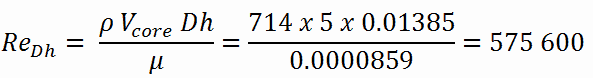
This fully satisfies the turbulent conditions.
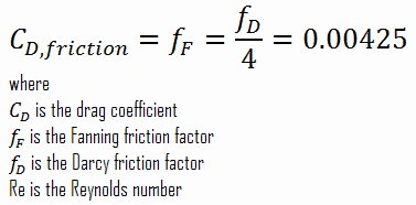
Calculation of the Skin Friction Coefficient
The friction factor for turbulent flow depends strongly on the relative roughness. It is determined by the Colebrook equation or can be determined using the Moody chart. The Moody chart for Re = 575 600 and ε/D = 5 x 10⁻⁴ returns following values:
- the Darcy friction factor is equal to fD = 0.017
- the Fanning friction factor is equal to fF = fD/4 = 0.00425
Therefore the skin friction coefficient is equal to:
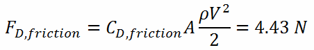
Calculation of the Drag Force
To calculate the drag force, we have to know:
- the skin friction coefficient, which is: CD,friction = 0.00425
- the area of pin surface, which is: A = π.d.h = 0.1169 m2
- the fluid density, which is: ρ = 714 kg/m3
- the core flow velocity, which is constant and equal to Vcore = 5 m/s
From the skin friction coefficient, which is equal to the Fanning friction factor, we can calculate the frictional component of the drag force. The drag force is given by:
Assuming that a fuel assembly can have, for example, 289 fuel pins (17×17 fuel assembly), the frictional component of the drag force is then of the order of kilonewtons. Moreover, this drag force originates purely from the skin friction on the fuel bundle. But typical PWR fuel assembly contains other components which influence the fuel assembly hydraulics:
- Fuel rods. Fuel rods contain fuel and burnable poisons.
- Top nozzle. Provides the mechanical support for the fuel assembly structure.
- Bottom nozzle. Provides the mechanical support for the fuel assembly structure.
- Spacing grid. Ensures an exact guiding of the fuel rods.
- Guide thimble tube. Vacant tube for control rods or in-core instrumentation.
As was written, the second component of the drag force is the form drag. Form drag, also known as pressure drag, arises because of the shape and size of the object. The pressure drag is proportional to the difference between the pressures acting on the front and back of the immersed body and the frontal area.