Heat exchangers are typically classified according to flow arrangement and type of construction.
- parallel-flow arrangement
- counter-flow arrangement
Heat transfer in a heat exchanger usually involves convection in each fluid and thermal conduction through the wall separating the two fluids. It is often convenient to work with an overall heat transfer coefficient, known as a U-factor, in analyzing heat exchangers. The U-factor is defined by an expression analogous to Newton’s law of cooling. Moreover, engineers also use the logarithmic mean temperature difference (LMTD) to determine the temperature driving force for heat transfer in heat exchangers.
The classic example of a heat exchanger is found in an internal combustion engine in which an engine coolant flows through radiator coils, and air flows past the coils, which cools the coolant and heats the incoming air. In power engineering, common applications of heat exchangers include steam generators, fan coolers, cooling water heat exchangers, and condensers. For example, a steam generator converts feedwater into steam from heat produced in a nuclear reactor core, and the steam produced drives the turbine.
Special Reference: John R. Thome, Engineering Data Book III. Wolverine Tube Inc. 2004.
Types of Heat Exchangers – Classification of Heat Exchangers
Heat exchangers are typically classified according to flow arrangement and type of construction. The simplest heat exchanger is one for which the hot and cold fluids move in the same or opposite directions, and this heat exchanger consists of two concentric pipes of different diameters.
- parallel-flow arrangement. In the parallel-flow arrangement, the hot and cold fluids enter at the same end, flow in the same direction, and leave at the same end.
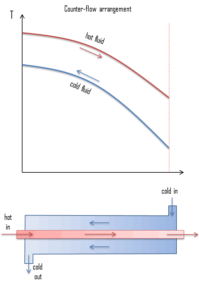
- counter-flow arrangement. In the counter-flow arrangement, the fluids enter at opposite ends, flow in opposite directions, and leave at opposite ends.
The figure represents the directions of fluid flow in the parallel and counter-flow exchangers. Under comparable conditions, more heat is transferred in a counter-flow arrangement than in a parallel flow heat exchanger. The temperature profiles of the two heat exchangers indicate two major disadvantages in the parallel-flow design.
- The large temperature difference at the ends causes large thermal stresses.
- The temperature of the cold fluid exiting the heat exchanger never exceeds the lowest temperature of the hot fluid.
The design of a parallel flow heat exchanger is advantageous when two fluids are required to be brought to nearly the same temperature.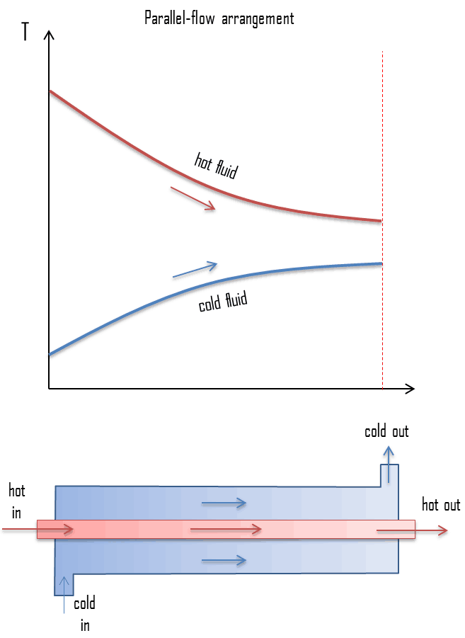
The heat transfer surface in heat exchangers can be arranged in several forms. Heat exchangers are therefore also classified as:
- Double pipe heat exchangers. Double pipe heat exchangers are cheap for design and maintenance, making them a good choice for small industries. One fluid flows inside the tube in these exchangers, and the other fluid flows outside. Although they are simple and cheap, their low efficiency coupled with the high space occupied in large scales has led modern industries to use more efficient heat exchangers like shells and tubes.
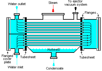
- Shell and tube heat exchangers. In their various construction modifications, shell and tube heat exchangers are probably the most widespread and commonly used basic heat exchanger configuration in the industry. Shell-and-tube heat exchangers are classified according to the number of shell and tube passes involved. Shell and tube heat exchangers are typically used for high-pressure applications (with pressures greater than 30 bar and temperatures greater than 260 °C). The shell and tube heat exchangers can withstand high pressures due to their shape. In this type of heat exchanger, several small bore pipes are fitted between two tube plates, and primary fluid flows through these tubes. The tube bundle is placed inside a shell, and the secondary fluid flows through the shell and over the surface of the tubes. In nuclear engineering, this design of heat exchangers is widely used, as in the case of steam generators, which are used to convert feedwater into steam from heat produced in a nuclear reactor core. The heat exchange surface must be maximized to increase the amount of heat transferred and the power generated. This is obtained by using tubes. Each steam generator can contain anywhere from 3,000 to 16,000 tubes, about 19mm in diameter.
- Plate heat exchangers. A plate heat exchanger is a type of heat exchanger that uses metal plates to transfer heat between two fluids. This arrangement is popular with heat exchangers using air or gas as well as lower velocity fluid flow. The classic example of a heat exchanger is found in an internal combustion engine in which an engine coolant flows through radiator coils, and air flows past the coils, which cools the coolant and heats the incoming air. Compared to shell and tube exchangers, the stacked-plate arrangement typically has lower volume and cost. Another difference between the two is that plate exchangers typically serve low to medium pressure fluids, compared to medium and high pressures of shell and tube.
Heat Exchanger Analysis – Heat Exchanger Calculation
Heat exchangers are commonly used in industry, and the proper design of a heat exchanger depends on many variables. Following terms and methods are widely used to select an appropriate heat exchanger.
Overall Heat Transfer Coefficient
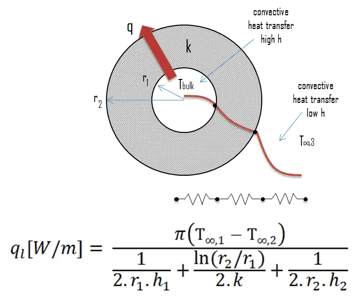
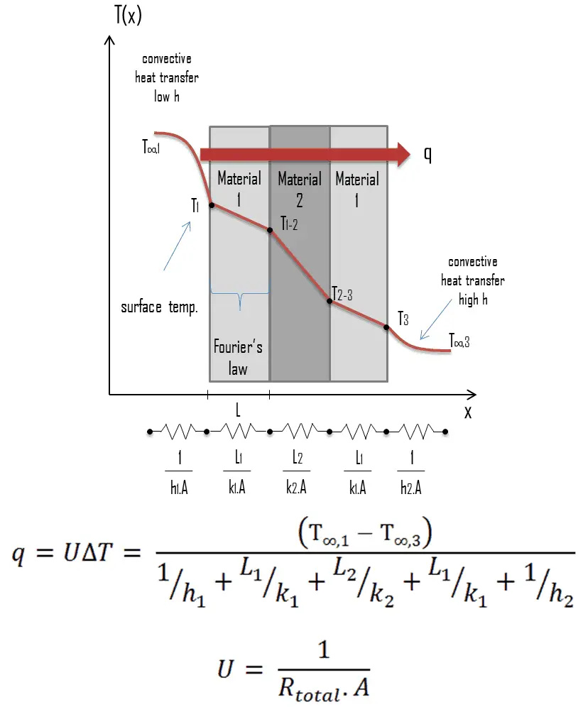 A heat exchanger typically involves two flowing fluids separated by a solid wall. Many of the heat transfer processes encountered in the industry involve composite systems and even involve a combination of both conduction and convection. Heat is first transferred from the hot fluid to the wall by convection, through the wall by conduction, and then to the cold fluid again by convection.
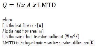
It is often convenient to work with an overall heat transfer coefficient, known as a U-factor with these composite systems. The U-factor is defined by an expression analogous to Newton’s law of cooling:

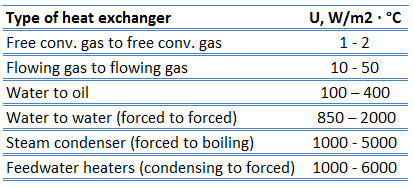 The overall heat transfer coefficient, U, is related to the total thermal resistance and depends on the geometry of the problem. For example, heat transfer in a steam generator involves convection from the bulk of the reactor coolant to the steam generator inner tube surface, conduction through the tube wall, and convection (boiling) from the outer tube surface to the secondary side fluid.
In cases of combined heat transfer for a heat exchanger, there are two values for h. The convective heat transfer coefficient (h) for the fluid film inside the tubes and a convective heat transfer coefficient for the fluid film outside the tubes. The tube wall’s thermal conductivity (k) and thickness (Δx) must also be accounted for.
Online monitoring of commercial heat exchangers is done by tracking the overall heat transfer coefficient because the overall heat transfer coefficient tends to decline over time due to fouling. By periodically calculating the overall heat transfer coefficient from exchanger flow rates and temperatures, the operator of the heat exchanger can estimate the lifetime of heat exchangers.
Logarithmic Mean Temperature Difference – LMTD
To solve certain heat exchanger problems, engineers often use a log mean temperature difference (LMTD), which is used to determine the temperature driving force for heat transfer in heat exchangers. LMTD is introduced because the temperature change that takes place across the heat exchanger from the entrance to the exit is not linear.
The heat transfer through the wall of a heat exchanger at a given location is given by the following equation:
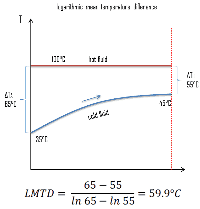 Here the value of the overall heat transfer coefficient can be assumed as a constant. On the other hand, the temperature difference continuously varies with location (especially in counter-flow arrangement). To determine the total heat flow, either the heat flow should be summed up using elemental areas and the temperature difference at the location. More conveniently, engineers can average the value of temperature difference. The heat exchanger equation can be solved much easier by defining a “Mean Temperature Difference” (MTD). It can be seen from the figure that the temperature difference varies along with the flow, and the arithmetic average may not be the real average, therefore. Engineers use the logarithmic mean temperature difference. The “Logarithmic Mean Temperature Difference” (LMTD) is a logarithmic average of the temperature difference between the hot and cold feeds at each end of the heat exchanger. The larger the LMTD, the more heat is transferred. It can be seen from the figure that the temperature difference varies along with the flow, and the arithmetic average may not be the real average.
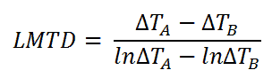
For a heat exchanger that has two ends (which we call “A” and “B”) at which the hot and cold streams enter or exit on either side, the LMTD is defined as:
The heat transfer is then given by:
This holds both for parallel-flow arrangement, where the streams enter from the same end, and for counter-flow arrangement, they enter from different ends.
In a cross-flow, where one system, usually the heat sink, has the same nominal temperature at all points on the heat transfer surface, a similar relation between exchanged heat and LMTD holds, but with a correction factor. A correction factor is also required for other more complex geometries, such as a shell and tube exchanger with baffles.
LMTD – Condensers and Boilers

Steam generators and condensers are also examples of components found in nuclear facilities where the concept of LMTD is needed to address certain problems. When the subcooled water enters the steam generator, it must be heated up to its boiling point, and then it must be evaporated. Because evaporation occurs at a constant temperature, it cannot be used as a single LMTD. In this case, the heat exchanger must be treated as a combination of two or three (when superheat occurs) heat exchangers.
Pinch Point – Heat Exchanger
Another interesting aspect of the design is that the temperature difference is known as ‘pinch’ can limit the performance of heat exchangers if the areas and flow rates are not properly designed. A pinch point is a location in a heat exchanger where the temperature difference between hot and cold fluid is minimum at that location.
NTU Effectiveness Method
The log means temperature difference (LMTD) method discussed in the previous section is easy to use in heat exchanger analysis when the inlet and the outlet temperatures of the hot and cold fluids are known or can be determined from an energy balance. Therefore, the LMTD method is very suitable for determining the size and performance of a heat exchanger.
When direct knowledge of the LMTD is not available, the NTU method (Number of Transfer Units method) can be used. This method is based on a dimensionless parameter called the heat transfer effectiveness, defined as:
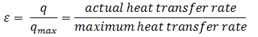
As can be seen, the effectiveness is the ratio between the actual heat transfer rate and the maximum possible heat transfer rate. To define the effectiveness of a heat exchanger, we must first determine the maximum possible heat transfer rate, qmax, for the heat exchanger.
Further reading:
- Fundamentals of Heat and Mass Transfer, 7th Edition. Theodore L. Bergman, Adrienne S. Lavine, Frank P. Incropera. John Wiley & Sons, Incorporated, 2011. ISBN: 9781118137253.
- Heat and Mass Transfer. Yunus A. Cengel. McGraw-Hill Education, 2011. ISBN: 9780071077866.
Example: Calculation of Heat Exchanger
 Consider a parallel-flow heat exchanger used to cool oil from 70°C to 40°C using water available at 30°C. The outlet temperature of the water is 36°C, and the rate of flow of oil is 1 kg/s. The specific heat of the oil is 2.2 kJ/kg K. The overall heat transfer coefficient U = 200 W/m2 K.
Calculate the logarithmic mean temperature difference. Determine the area of this heat exchanger required for this performance.
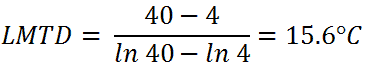
- LMTD
The logarithmic mean temperature difference can be calculated simply using its definition:
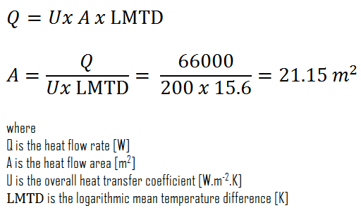
- Area of Heat Exchanger
To calculate the area of this heat exchanger, we have to calculate the heat flow rate using the mass flow rate of oil and LMTD.

The required area of this heat exchanger can be then directly calculated using the general heat transfer equation:
Recuperator and Regenerative Heat Exchanger
In general, the heat exchangers used in regeneration may be classified as either regenerators or recuperators.
- A regenerator is a type of heat exchanger where heat from the hot fluid is intermittently stored in a thermal storage medium before it is transferred to the cold fluid. It has a single flow path where the hot and cold fluids alternately pass through.
- A recuperator is a type of heat exchanger that has separate flow paths for each fluid along its passages, and heat is transferred through the separating walls. Recuperators (e.g., economizers) are often used in power engineering to increase the overall efficiency of thermodynamic cycles, for example, in a gas turbine engine. The recuperator transfers some of the waste heat in the exhaust to the compressed air, thus preheating it before entering the combustion chamber. Many recuperators are designed as counter-flow heat exchangers.
Heat Regeneration
In steam turbines theory, significant increases in the thermal efficiency of the steam turbine can be achieved by reducing the amount of fuel that must be added to the boiler. This can be done by transferring heat (e.g., partially expanded steam) from certain steam turbine sections, which is normally well above the ambient temperature, to the feedwater. This process is known as heat regeneration, and a variety of heat regenerators can be used for this purpose. Sometimes engineers use the term economizer, that is, heat exchanger intended to reduce energy consumption, especially in case of preheating of a fluid.
As can be seen in the article “Steam Generator”, the feedwater (secondary circuit) at the inlet of the steam generator may have about ~230°C (446°F)and then is heated to the boiling point of that fluid (280°C; 536°F; 6,5MPa)and evaporated. But the condensate at the condenser outlet may have about 40°C, so the heat regeneration in typical PWR is significant:
- Heat regeneration increases the thermal efficiency since more of the heat flow into the cycle occurs at a higher temperature.
- Heat regeneration causes a decrease in the mass flow rate through a low-pressure stage of the steam turbine, thus increasing LP Isentropic Turbine Efficiency. Note that the steam has a very high specific volume at the last stage of expansion.
- Heat regeneration causes an increase in working steam quality since the drains are situated at the periphery of the turbine casing, where is a higher concentration of water droplets.