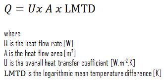
The heat transfer through the wall of a heat exchanger at a given location is given by the following equation:

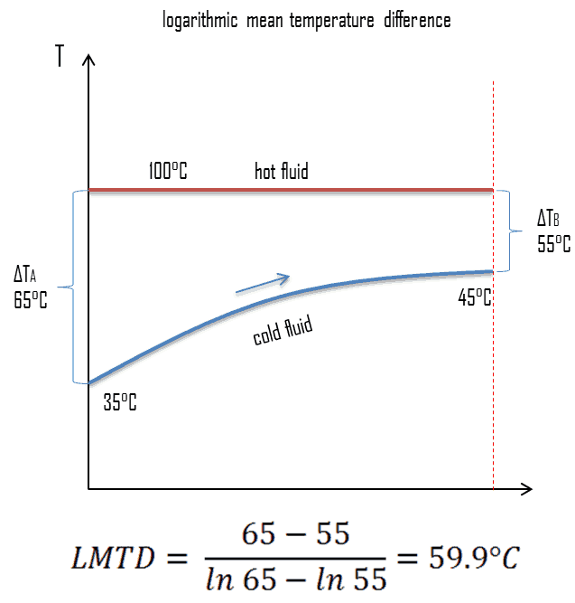 Here, the overall heat transfer coefficient value can be assumed as a constant. On the other hand, the temperature difference continuously varies with location (especially in counter-flow arrangement). To determine the total heat flow, either the heat flow should be summed up using elemental areas and the temperature difference at the location. More conveniently, engineers can average the value of temperature difference. The heat exchanger equation can be solved much easier by defining a “Mean Temperature Difference” (MTD). It can be seen from the figure that the temperature difference varies along with the flow, and the arithmetic average may not be the real average; therefore, engineers use the logarithmic mean temperature difference. The “Logarithmic Mean Temperature Difference“ (LMTD) is a logarithmic average of the temperature difference between the hot and cold feeds at each end of the heat exchanger. The larger the LMTD, the more heat is transferred. It can be seen from the figure that the temperature difference varies along with the flow, and the arithmetic average may not be the real average.
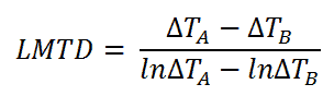
For a heat exchanger that has two ends (which we call “A” and “B”) at which the hot and cold streams enter or exit on either side, the LMTD is defined as:
The heat transfer is then given by:
This holds both for parallel-flow arrangement, where the streams enter from the same end, and for counter-flow arrangement, they enter from different ends.
In a cross-flow, where one system, usually the heat sink, has the same nominal temperature at all points on the heat transfer surface, a similar relation between exchanged heat and LMTD holds, but with a correction factor. A correction factor is also required for other more complex geometries, such as a shell and tube exchanger with baffles.
LMTD – Condensers and Boilers

Steam generators and condensers are also examples of components found in nuclear facilities where the concept of LMTD is needed to address certain problems. When the subcooled water enters the steam generator, it must be heated up to its boiling point, and then it must be evaporated. Because evaporation occurs at a constant temperature, it cannot be used as a single LMTD. In this case, the heat exchanger must be treated as a combination of two or three (when superheat occurs) heat exchangers.
Example: Calculation of Heat Exchanger
 Consider a parallel-flow heat exchanger used to cool oil from 70°C to 40°C using water available at 30°C. The outlet temperature of the water is 36°C, and the rate of flow of oil is 1 kg/s. The specific heat of the oil is 2.2 kJ/kg K. The overall heat transfer coefficient U = 200 W/m2 K.
Calculate the logarithmic mean temperature difference. Determine the area of this heat exchanger required for this performance.
- LMTD
The logarithmic mean temperature difference can be calculated simply using its definition:
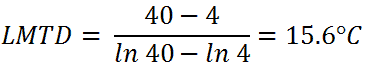
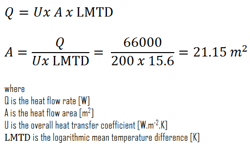
- Area of Heat Exchanger
To calculate the area of this heat exchanger, we have to calculate the heat flow rate using the mass flow rate of oil and LMTD.

The required area of this heat exchanger can be then directly calculated using the general heat transfer equation: