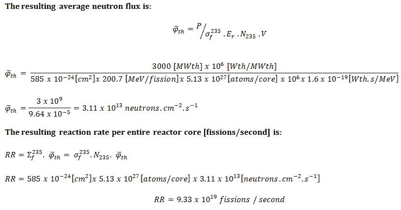
There is a direct proportionality between the neutron flux and the reactor thermal power in nuclear reactors. This proportionality is determined by the fission reaction rate per unit volume (RR = Ф . Σ). The fission reaction rate within a nuclear reactor is controlled by several factors. For simplicity, let assume that the fissionable material is uniformly distributed in the reactor. In this case, the macroscopic cross-sections are independent of position. Multiplying the fission reaction rate per unit volume (RR = Ф . Σ) by the total volume of the core (V) gives us the total number of reactions occurring in the reactor core per unit time. But we also know the amount of energy released per one fission reaction to be about 200 MeV/fission. Now, it is possible to determine the rate of energy release (power) due to the fission reaction. It is given by the following equation:
P = RR . Er . V = Ф . Σf . Er . V = Ф . NU235 . σf235 . Er . V
where:
P – reactor power (MeV.s-1)
Ф – neutron flux (neutrons.cm-2.s-1)
σ – microscopic cross section (cm2)
N – atomic number density (atoms.cm-3)
Er – the average recoverable energy per fission (MeV / fission)
V – total volume of the core (m3)
Solution:
The amount of fissile 235U per the volume of the reactor core.
m235 [g/core] = 100 [metric tons] x 0.02 [g of 235U / g of U] . 106 [g/metric ton] = 2 x 10⁶ grams of 235U per the volume of the reactor core
The atomic number density of 235U in the volume of the reactor core:
N235 . V = m235 . NA / M235
= 2 x 10⁶ [g 235 / core] x 6.022 x 10²³ [atoms/mol] / 235 [g/mol]
= 5.13 x 1027 atoms / core
The microscopic fission cross-section of 235U (for thermal neutrons):
σf235 = 585 barns
The average recoverable energy per 235U fission:
Er = 200.7 MeV/fission
In general, nuclear fission results in the release of enormous quantities of energy. The amount of energy depends strongly on the nucleus to be fissioned and also depends strongly on the kinetic energy of an incident neutron. To calculate the power of a reactor, it is necessary to precisely identify the individual components of this energy. At first, it is important to distinguish between the total energy released and the energy that can be recovered in a reactor.
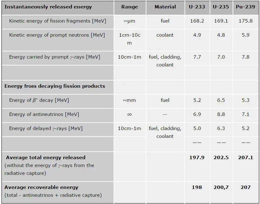 The total energy released in fission can be calculated from binding energies of the initial target nucleus to be fissioned and binding energies of fission products. But not all the total energy can be recovered in a reactor. For example, about 10 MeV is released in the form of neutrinos (in fact, antineutrinos). Since the neutrinos are weakly interacting (with an extremely low cross-section of any interaction), they do not contribute to the energy that can be recovered in a reactor.
As shown in the table, the total energy released in a reactor is about 210 MeV per 235U fission, distributed as shown in the table. In a reactor, the average recoverable energy per fission is about 200 MeV, the total energy minus the energy of antineutrinos radiated away. This means that about 3.1⋅1010 fissions per second are required to produce a power of 1 W. Since 1 gram of any fissile material contains about 2.5 x 10²¹ nuclei, the fissioning of 1 gram of fissile material yields about 1 megawatt-day (MWd) of heat energy.
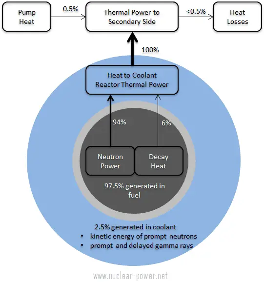
As can be seen from the description of the individual components of the total energy released during the fission reaction, there is a significant amount of energy generated outside the nuclear fuel (outside fuel rods). Especially the kinetic energy of prompt neutrons is largely generated in the coolant (moderator). This phenomenon needs to be included in the nuclear calculations.
For LWR, it is generally accepted that about 2.5% of total energy is recovered in the moderator. This fraction of energy depends on the materials, their arrangement within the reactor, and thus on the reactor type.
It must also be added the other reactor internals must be cooled sufficiently to prevent overheating of their construction materials. One of the most exposed components is the neutron reflector, especially the heavy reflector. While acting as a neutron shield, the heavy reflector is heated due to the absorption of gamma radiation. The heat in the reflector is removed by water flowing through cooling channels drilled through the reflector to avoid overheating.
See also: Energy release per fission
See also: Residual Heat
 Since the electromagnetic interaction extends over some distance, it is not necessary for the light or heavy charged particle to make a direct collision with an atom. They can transfer energy simply by passing close by. Heavy charged particles, such as fission fragments or alpha particles, interact with matter primarily through coulomb forces between their positive charge and the negative charge of the electrons from atomic orbitals. On the other hand, the internal energy of an atom is quantized; therefore, only a certain amount of energy can be transferred. In general, charged particles transfer energy mostly by:
- Excitation. The charged particle can transfer energy to the atom, raising electrons to higher energy levels.
- Ionization. Ionization can occur when the charged particle has enough energy to remove an electron, resulting in the creation of ion pairs in surrounding matter.
The creation of pairs requires energy, which is lost from the kinetic energy of the charged particle, causing it to decelerate. The positive ions and free electrons created by the passage of the charged particle will then reunite, releasing energy in the form of heat (e.g., vibrational energy or rotational energy of atoms). This principle is how fission fragments heat fuel in the reactor core. There are considerable differences in the ways of energy loss and scattering between the passage of light-charged particles such as positrons and electrons and heavy charged particles such as fission fragments, alpha particles, muons. Most of these differences are based on the different dynamics of the collision process. In general, when a heavy particle collides with a much lighter particle (electrons in the atomic orbitals), the laws of energy and momentum conservation predict that only a small fraction of the massive particle’s energy can be transferred to the less massive particle. The actual amount of transferred energy depends on how closely the charged particles pass through the atom, and it also depends on restrictions from the quantization of energy levels.
The distance required to bring the particle to rest referred to as its range. The range of fission fragments in solids amounts to only a few microns, and thus most of the energy of fission is converted to heat very close to the point of fission. In the case of gases, the range increases to a few centimeter’s independence of gas parameters (density, type of gas, etc.) The trajectory of heavy charged particles is not greatly affected because they interact with light atomic electrons. Other charged particles, such as the alpha particles, behave similarly with one exception – for lighter charged particles, the ranges are somewhat longer.
Temperature Profile – Nuclear Fuel
 Most PWRs use uranium fuel, which is in the form of uranium dioxide. Uranium dioxide is a black semiconducting solid with very low thermal conductivity. On the other hand, uranium dioxide has a very high melting point and has well-known behavior. The UO2 is pressed into cylindrical pellets, and these pellets are then sintered into the solid.
These cylindrical pellets are then loaded and encapsulated within a fuel rod (or fuel pin) made of zirconium alloys due to their very low absorption cross-section (unlike stainless steel). The surface of the tube, which covers the pellets, is called fuel cladding.
See also: Thermal Conduction of Uranium Dioxide
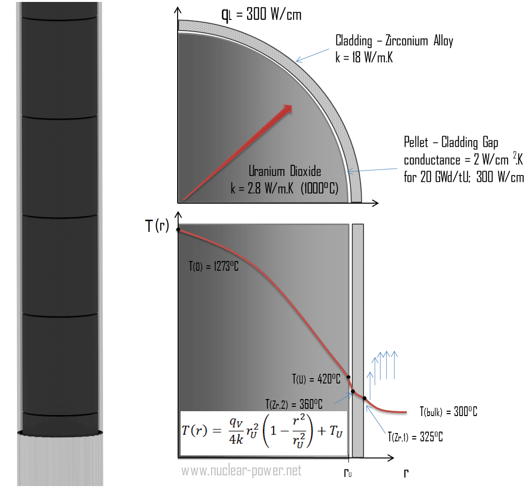
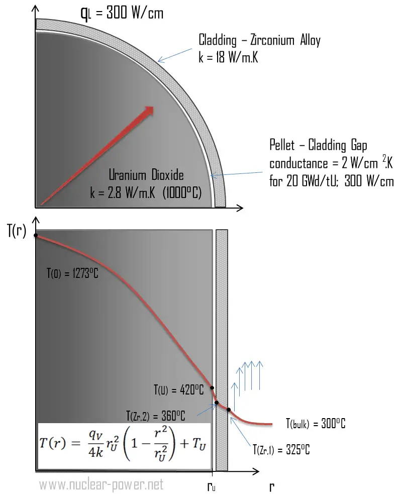
The thermal and mechanical behavior of fuel pellets and fuel rods constitute one of three key core design disciplines. Nuclear fuel is operated under inhospitable conditions (thermal, radiation, mechanical) and must withstand more than normal conditions operation. For example, temperatures in the center of fuel pellets reach more than 1000°C (1832°F), accompanied by fission-gas releases. Therefore detailed knowledge of temperature distribution within a single fuel rod is essential for the safe operation of nuclear fuel. This section will study the heat conduction equation in cylindrical coordinates using Dirichlet boundary conditions with given surface temperature (i.e., using Dirichlet boundary condition). Comprehensive analysis of fuel rod temperature profile will be studied separately.
The temperature in the centerline of a fuel pellet
Consider the fuel pellet of radius rU = 0.40 cm, in which there is uniform and constant heat generation per unit volume, qV [W/m3]. Instead of volumetric heat rate qV [W/m3], engineers often use the linear heat rate, qL [W/m], representing the heat rate of one meter of a fuel rod. The linear heat rate can be calculated from the volumetric heat rate by:
![]()
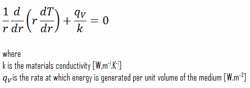
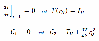
The centreline is taken as the origin for r-coordinate. Due to symmetry in the z-direction and azimuthal direction, we can separate variables and simplify this problem into a one-dimensional problem. Thus, we will only solve for the temperature as a function of radius, T(r). For constant thermal conductivity, k, the appropriate form of the cylindrical heat equation, is:
The general solution of this equation is:
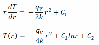
where C1 and C2 are the constants of integration.
 Calculate the temperature distribution, T(r), in this fuel pellet, if:
- the temperature at the surface of the fuel pellet is TU = 420°C
- the fuel pellet radius rU = 4 mm.
- the averaged material’s conductivity is k = 2.8 W/m.K (corresponds to uranium dioxide at 1000°C)
- the linear heat rate is qL = 300 W/cm and thus the volumetric heat rate is qV = 597 x 106 W/m3
In this case, the surface is maintained at given temperatures TU. This corresponds to the Dirichlet boundary condition. Moreover, this problem is thermally symmetric, and therefore we may also use thermal symmetry boundary conditions. The constants may be evaluated using substitution into the general solution and are of the form:
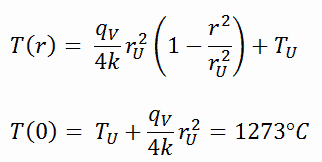
The resulting temperature distribution and the centerline (r = 0) temperature (maximum) in this cylindrical fuel pellet at these specific boundary conditions will be:
The radial heat flux at any radius, qr [W.m-1], in the cylinder may, of course, be determined by using the temperature distribution and with Fourier’s law. Note that, with heat generation, the heat flux is no longer independent of r.
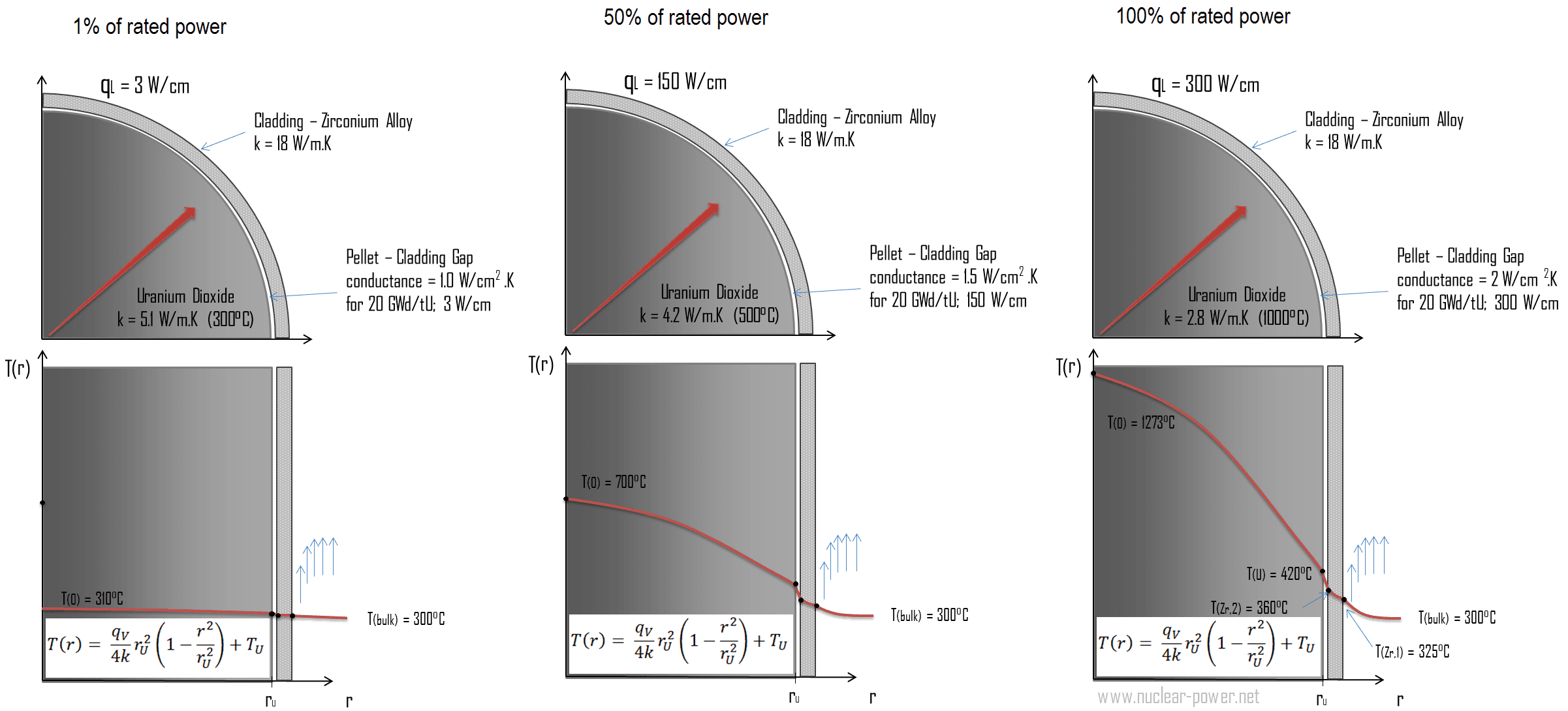
The following figure shows the temperature distribution in the fuel pellet at various power levels.
______
The temperature in an operating reactor varies from point to point within the system. Consequently, there is always one fuel rod and one local volume hotter than all the rest. The peak power limits must be introduced to limit these hot places. The peak power limits are associated with a boiling crisis and conditions that could cause fuel pellet melt. However, metallurgical considerations place upper limits on the temperature of the fuel cladding and the fuel pellet. Above these temperatures, there is a danger that the fuel may be damaged. One of the major objectives in the design of nuclear reactors is to remove the heat produced at the desired power level while assuring that the maximum fuel temperature and the maximum cladding temperature are always below these predetermined values.