A major source of heat loss from a house is through walls and facades. Facade insulation is a thermally insulated, protective, decorative exterior cladding procedure involving the use of expanded polystyrene insulation, glass or rock wool, polyurethane foam, or phenolic foam, topped off with a reinforced cement-based, mineral or synthetic finish and plaster.
The purpose of facade insulation is to reduce the overall heat transfer coefficient by adding materials with low thermal conductivity. External wall insulation in buildings is an important factor in achieving thermal comfort for its occupants. External wall insulation, as well as other types of insulation, reduce unwanted heat loss and also reduce unwanted heat gain. They can significantly decrease the energy demands of heating and cooling systems. It must be added that no material can completely prevent heat losses. Heat losses can only be minimized.
Insulation Materials
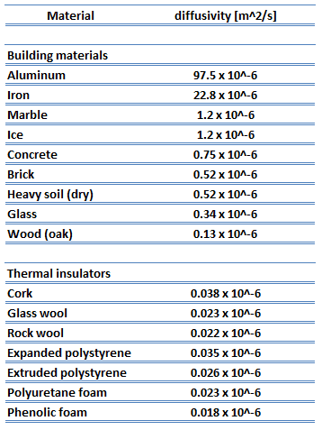 As was written, thermal insulation is based on the use of substances with very low thermal conductivity. These materials are known as insulation materials. Common insulation materials are wool, fiberglass, rock wool, polystyrene, polyurethane, goose feather, etc. Therefore, these materials are very poor conductors of heat and are good thermal insulators.
It must be added that thermal insulation is primarily based on the very low thermal conductivity of gases. Gases possess poor thermal conduction properties compared to liquids and solids and thus make a good insulation material if they can be trapped (e.g., in a foam-like structure). Air and other gases are generally good insulators. But the main benefit is in the absence of convection. Therefore, many insulation materials (e.g., polystyrene) function simply by having many gas-filled pockets, which prevent large-scale convection. In all types of thermal insulation, evacuation of the air in the void space will further reduce the overall thermal conductivity of the insulator.
Alternation of gas pocket and solid material causes heat to transfer through many interfaces, causing a rapid decrease in heat transfer coefficient.
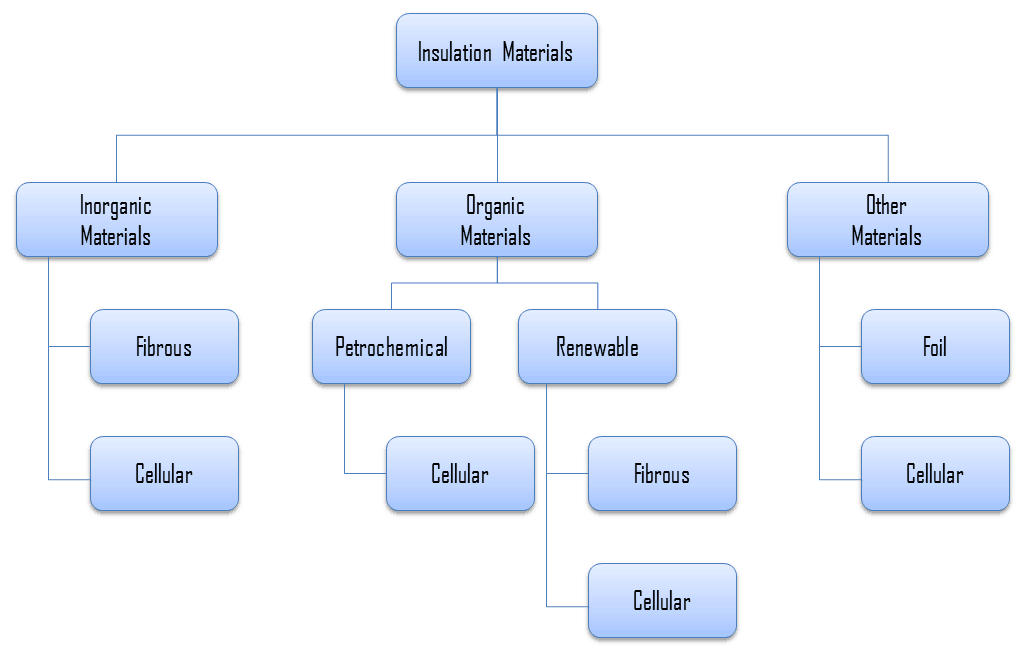
For insulation materials, three general categories can be defined. These categories are based on the chemical composition of the base material from which the insulating material is produced.
In further reading, there is a brief description of these types of insulation materials.
Inorganic Insulation Materials
As can be seen from the figure, inorganic materials can be classified accordingly:
- Fibrous materials
- Cellular materials
- Calcium silicate
- Cellular glass
Organic Insulation Materials
The organic insulation materials treated in this section are all derived from a petrochemical or renewable feedstock (bio-based). Almost all of the petrochemical insulation materials are in the form of polymers. As can be seen from the figure, all petrochemical insulation materials are cellular, and material is cellular when the material’s structure consists of pores or cells. On the other hand, many plants contain fibers for their strength. Therefore almost all the bio-based insulation materials are fibrous (except expanded cork, which is cellular).
Organic insulation materials can be classified accordingly:
- Petrochemical materials (oil/coal-derived)
- Renewable materials (plant/animal-derived)
- Cellulose
- Cork
- Woodfibre
- Hemp fibre
- Flax wool
- Sheeps wool
- Cotton insulation
Other Insulation Materials
Example of Insulation – Polystyrene
Generally, polystyrene is a synthetic aromatic polymer made from the monomer styrene, derived from benzene and ethylene, both petroleum products. Polystyrene can be solid or foamed. Polystyrene is a colorless, transparent thermoplastic that is commonly used to make foam board or beadboard insulation and a type of loose-fill insulation consisting of small beads of polystyrene. Polystyrene foams are 95-98% air. Polystyrene foams are good thermal insulators and are often used as building insulation materials, such as insulating concrete forms and structural insulated panel building systems. Expanded (EPS) and extruded polystyrene (XPS) are both made from polystyrene. Still, EPS is composed of small plastic beads fused, and XPS begins as a molten material pressed out of a form into sheets. XPS is most commonly used as foam board insulation.
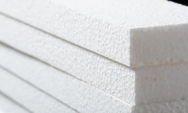 Expanded polystyrene (EPS) is a rigid and tough, closed-cell foam. Building and construction applications account for around two-thirds of the demand for expanded polystyrene, and it is used for insulation (cavity) on walls, roofs, and concrete floors. Due to its technical properties such as low weight, rigidity, and formability, expanded polystyrene can be used in a wide range of applications, for example, trays, plates, and fish boxes.
Although both expanded and extruded polystyrene have a closed-cell structure, they are permeable by water molecules and can not be considered a vapor barrier. There are interstitial gaps between the expanded closed-cell pellets in expanded polystyrene that form an open network of channels between the bonded pellets. If the water freezes into ice, it expands and can cause polystyrene pellets to break off from the foam.
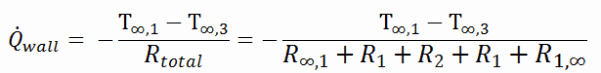
Example – Heat Loss through a Wall
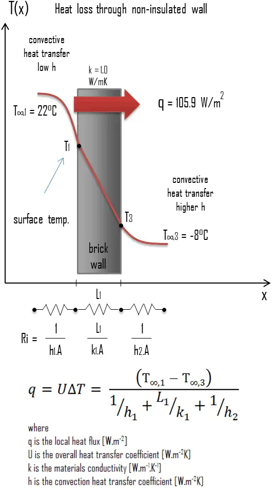 A major source of heat loss from a house is through walls. Calculate the rate of heat flux through a wall 3 m x 10 m in the area (A = 30 m2). The wall is 15 cm thick (L1), and it is made of bricks with thermal conductivity of k1 = 1.0 W/m.K (poor thermal insulator). Assume that the indoor and the outdoor temperatures are 22°C and -8°C, and the convection heat transfer coefficients on the inner and the outer sides are h1 = 10 W/m2K and h2 = 30 W/m2K, respectively. Note that these convection coefficients strongly depend especially on ambient and interior conditions (wind, humidity, etc.).
- Calculate the heat flux (heat loss) through this non-insulated wall.
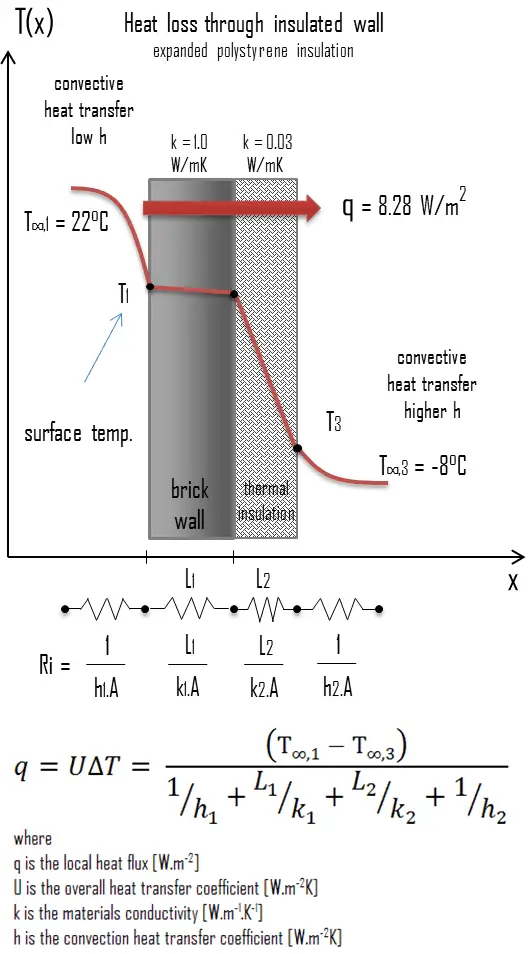
- Now assume thermal insulation on the outer side of this wall. Use expanded polystyrene insulation 10 cm thick (L2) with the thermal conductivity of k2 = 0.03 W/m.K and calculate the heat flux (heat loss) through this composite wall.
Solution:
Many heat transfer processes involve composite systems and even involve a combination of conduction and convection. It is often convenient to work with an overall heat transfer coefficient, known as a U-factor with these composite systems. The U-factor is defined by an expression analogous to Newton’s law of cooling:

The overall heat transfer coefficient is related to the total thermal resistance and depends on the geometry of the problem.
- bare wall
Assuming one-dimensional heat transfer through the plane wall and disregarding radiation, the overall heat transfer coefficient can be calculated as:
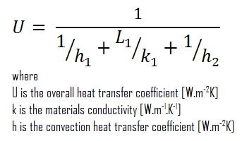
The overall heat transfer coefficient is then:
U = 1 / (1/10 + 0.15/1 + 1/30) = 3.53 W/m2K
The heat flux can be then calculated simply as:
q = 3.53 [W/m2K] x 30 [K] = 105.9 W/m2
The total heat loss through this wall will be:
qloss = q . A = 105.9 [W/m2] x 30 [m2] = 3177W
- composite wall with thermal insulation
Assuming one-dimensional heat transfer through the plane composite wall, no thermal contact resistance, and disregarding radiation, the overall heat transfer coefficient can be calculated as:
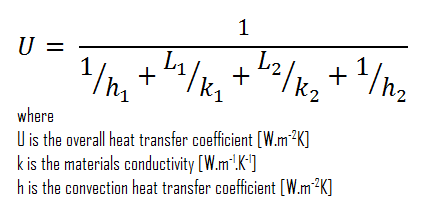
 The overall heat transfer coefficient is then:
U = 1 / (1/10 + 0.15/1 + 0.1/0.03 + 1/30) = 0.276 W/m2K
The heat flux can be then calculated simply as:
q = 0.276 [W/m2K] x 30 [K] = 8.28 W/m2
The total heat loss through this wall will be:
qloss = q . A = 8.28 [W/m2] x 30 [m2] = 248 W
As can be seen, adding a thermal insulator causes a significant decrease in heat losses. It must be added that adding the next layer of the thermal insulator does not cause such high savings. This can be better seen from the thermal resistance method, which can be used to calculate the heat transfer through composite walls. The rate of steady heat transfer between two surfaces is equal to the temperature difference divided by the total thermal resistance between those two surfaces.