Non-destructive testing, NDT, is a very broad group of structural or material inspections, and as the name implies, these inspections do not destroy the material/structure being examined. NDT plays a critical role in assuring that structural components and systems perform their function in a reliable and cost-effective fashion. Because NDT does not permanently alter the article being inspected, it is a highly valuable technique that can save both money and time in product evaluation, troubleshooting, and research. NDT technicians and engineers define and implement tests that locate and characterize material conditions and flaws that might otherwise cause serious accidents, such as planes to crash, reactors failing, trains derailing, pipelines bursting, and a variety of troubling events.
This concept is extended, known as Non-Destructive Evaluation (NDE) when combined with an assessment of the significance of any defects found. However, they are both terms often used interchangeably. Some testing methods must be conducted in a laboratory setting. Others may be adapted for use in the field. Several commonly employed NDT techniques and their characteristics are described below.
Classification of NDT Methods
The variety of techniques available can also be divided into two groups: surface methods, which are used to identify surface and near-surface defects such as cracks and surface porosity, and subsurface methods, which can be used to detect defects that lie under thematerial’ss surface.
- Surface methods
- Subsurface methods
Visual and Optical Testing
Visual inspection involves using aninspector’ss eyes to look for defects, such as scratches, presence of debris, corrosion, or oxidation. The inspector may also use special tools such as magnifying glasses, mirrors, or borescopes to gain access and inspect the subject area more closely. In nuclear power plants, an extensive fuel inspection programme (e.g., visual inspections, oxide layer measurements, eddy-current tests of control rods) is carried out underwater and supervised by the regulatory body. So visual testing is usually a part of the Post Irradiation Examination. Visual examinations are also very common in the aircraft industry, where over 80 percent of the inspections done to an aircraft are visual inspections, is often used as an initial screening method to detect gross defects and target subsequent testing by other methods.
Eddy-current Testing
Eddy current testing is one of the most common electromagnetic testing NDT methods. It uses induced electrical currents to detect defects. Essentially, the technique uses a coil (ECT probe) carrying an alternating current as a transducer. This produces an alternating magnetic field parallel to the axis of the coil, which in turn induces eddy currents on the test object’s surface. These eddy currents set up a magnetic field opposing that produced by the coil, thus changing the impedance of the coil. Interruptions in the flow of eddy currents caused by imperfections, dimensional changes, or changes in the material’s condmaterial’s permeability properties are detected.
Most eddy current testing is based on the measurement of the coil impedance, though it is possible to measure the magnetic field directly. ECT has a very wide range of applications. Since ECT is electrical in nature, it is limited to a conductive material. There are also physical limits to generating eddy currents and penetration depth (skin depth). In general, this technique is used to inspect relatively small areas and is, therefore, better suited for inspecting areas where damage is already suspected. It nevertheless has a variety of applications: from measuring material thickness to detecting corrosion damage. In nuclear power plants, eddy-current methods provide the best in-service inspection method for steam generator tubing. The following components are required to perform Eddy Current testing: an Eddy Current tester, a remote positioning device, and an eddy current probe drive control system.
The disadvantages of this technique are that it is sensitive to lift-off, it is a point test, so scanning is required for large areas, and it is generally limited to near-surface defects of conducting materials.
Liquid Penetrant Testing
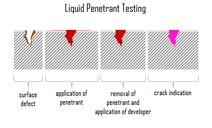 Liquid penetrant inspection (LPI), also called dye penetrant inspection (DP), is a widely applied NDT method which is used to check surface-breaking defects in all non-porous materials (metals, plastics, or ceramics). It is probably one of the most widely used NDT techniques. Test and pre-cleaned objects are coated with visible or fluorescent dye solution. After 5 to 30 minutes, depending on the material inspected, excess penetrant is removed from the surface, and a developer in liquid or powder form is applied. The developer acts as a blotter, drawing trapped penetrant out of imperfections open to the surface. This developer absorbs penetrant drawn from discontinuities and reveals a vivid color contrast between the penetrant and developer (usually red on white). With fluorescent dyes, ultraviolet light is used to make the bleed out fluoresce brightly, thus allowing imperfections to be readily seen.
LPI detect casting, forging, and welding surface defects such as hairline cracks, surface porosity, leaks in new products, and fatigue cracks on in-service components.
Magnetic-particle Inspection
Magnetic-particle inspection is one of the NDT processes for detecting surface and near-surface imperfections and material discontinuities. This method is accomplished by inducing a magnetic field in a ferromagnetic material and then dusting the surface with fine ferromagnetic particles (either dry or suspended in liquid). These are attracted to an area of flux leakage and form what is known as an indication, which is evaluated to determine its nature, cause, and course of action, if any. Although this technique reveals the location of the defects, it is often unable to determine their depth.
The piece can be magnetized by direct or indirect magnetization. Direct magnetization occurs when the electric current is passed through the test object, and a magnetic field is formed in the material. Indirect magnetization occurs when no electric current is passed through the test object, but a magnetic field is applied from an outside source. It has the major drawback of requiring to magnetize (and frequently demagnetize) the component.
Ultrasonic Testing
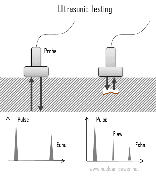 Ultrasonic testing is a broad group of NDT techniques based on the propagation of ultrasonic waves in the object or material tested. The most commonly used ultrasonic testing technique is pulse echo, wherein high-frequency sound wave beams (normally ranging from 1-5 MHz) are introduced into a test object, and reflections (echoes) are returned to a receiver from internal imperfections or the part’s geometrical surfaces.
The bpart’sethod of ultrasonic testing is transforming a voltage pulse into an ultrasonic pulse using a transducer. Transducers used for traditional UT consist of a piezoelectric crystal enclosed within a plastic or stainless steel housing. The piezoelectric crystals expand when electrically charged, thus generating an acoustic wave. The signal travels through the object concerning its geometry and existing defects and then is either transmitted to another transducer or reflected to the original transducer. Defects are detected if they produce a change in the acoustic impedance in the path of the ultrasonic beam. An open crack filled with air has very low acoustic impedance, reflecting virtually all the acoustic energy incident on it. Hence, the sound waves travel through the material and are reflected from cracks or flaws. Defects and flaws affect its way, and a small portion of the pulse will be sent back to the transducer/receiver before it hits the end of the object.
Since the speed of sound in the parent material is known, the reflected sound energy is then displayed versus time and analyzed to define the presence and location of flaws or discontinuities.
Advantages and Disadvantages of Ultrasonic Testing
The advantages and disadvantages of the ultrasonic testing method are as follows:
Advantages:
- UT is flexible, portable, and has high penetration depth.
- High sensitivity, permitting the detection of extremely small flaws.
- It is applicable in a wide range of industries.
- Some capability of estimating the size, orientation, shape, and nature of defects.
- Unlike radiographic testing, there is no health or environmental risk involved.
Disadvantages:
- It requires highly-trained operators and requires careful attention from experienced technicians.
- Unable or not efficient in detecting planar defects that is in parallel with the direction of sound wave.
- Parts that are rough, irregular in shape, very small or thin, or not homogeneous are difficult to inspect.
- It can be very expensive.
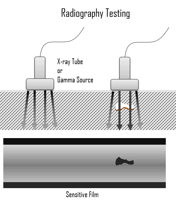
Radiographic Testing
Radiographic testing (RT) involves penetrating gamma or X-radiation to examine parts and products for imperfections. It is one of the conventional NDT methods that has been in use over decades and is still being used by companies worldwide.
- X-rays, also known as X-radiation, refer to electromagnetic radiation of high energies (no rest mass, no charge). Most X-rays have a wavelength ranging from 0.01 to 10 nanometers (3×10¹⁶ Hz to 3×10¹⁹ Hz), corresponding to energies from of 100 eV to 100 keV. X-ray wavelengths are shorter than those of UV rays and typically longer than those of gamma rays. The distinction between X-rays and gamma rays is not so simple and has changed in recent decades. According to the currently valid definition, X-rays are emitted by electrons outside the nucleus, while gamma rays are emitted by the nucleus. X-rays can be generated by an X-ray tube, a vacuum tube that uses a high voltage to accelerate the electrons released by a hot cathode to a high velocity. Upon striking the target, the accelerated electrons are abruptly stopped, and X-rays and heat are generated.
- Gamma rays, also known as gamma radiation, refer to electromagnetic radiation (no rest mass, no charge) of very high energies. Since the gamma rays are in substance only very high-energy photons, they are very penetrating matter and are thus biologically hazardous. Gamma rays can travel thousands of feet in the air and easily pass through the human body. Gamma rays are emitted by unstable nuclei in their transition from a high-energy state to a lower state, known as gamma decay. In most practical laboratory sources, the excited nuclear states are created in the decay of a parent radionuclide, therefore, a gamma decay typically accompanies other forms of decay, such as alpha or beta decay.
In general, RT is a method of inspecting materials for hidden subsurface defects by using the ability of X-rays or gamma rays to penetrate various materials of various thicknesses. The intensity of the radiation that penetrates and passes through the material is either captured by:
- a radiation-sensitive film (Film Radiography)
- a planer array of radiation-sensitive sensors (Real-time Radiography).
Principle of Operation
 The radiation source can either be an X-ray machine or a radioactive source (Ir-192, Co-60, or in rare cases, Cs-137). The choice between X-rays and gamma radiation depends on factors such as thickness, contrast level, etc. For example, X-rays typically work with a lower amount of energy than gamma rays. The thickness is another parameter that influences the results. For example, at thicknesses more than 50 mm, the use of gamma rays increases significantly.
Radiation is directed through a part and onto film or other imaging media, and the resulting radiograph shows the dimensional features of the part. Both in X-rays and gamma radiation, as the radiation passes more through the material, the darker the film becomes on the image produced,. On the contrary, the more the ray is absorbed by the material,, the lighter the image is in those spots. Therefore, possible imperfections are indicated as density changes on the film in the same manner as a medical X-ray shows broken bones.
Radiographic testing is commonly used for weld verification in various industrial applications. In manufacturing, welds are commonly used to join two or more metal parts. The effects of welding on the material surrounding the weld can be detrimental —depending on the materials used and the heat input of the welding process used. The HAZ can be of varying size and strength. For example, the base metal must reach a certain temperature during the welding process, must cool at a specific rate, and must be welded with compatible materials, or the joint may not be strong enough to hold the parts together, or cracks may form in the weld causing it to fail. Defects usually encountered include incomplete penetration, incomplete fusion, undercutting, porosity, and longitudinal cracking. These defects could cause a structure to break or a pipeline to rupture. Welds may be tested using NDT techniques such as industrial radiography or industrial CT scanning using X-rays or gamma rays, ultrasonic testing, liquid penetrant testing, magnetic particle inspection, or via eddy current.
Advantages and Disadvantages
Advantages:
- It has very few material limitations.
- Detection of internal defects for thick materials (e.g., pipelines).
- Minimal or no part preparation is required.
- One of the major advantages of RT is its documentation capability, and RT provides images of the object under inspection.
- The probability of misinterpretation of results is minimized since multiple operators can review each image.
Disadvantages:
- The impact of radiation on health and the environment can be considered one of the major disadvantages of radiographic testing since a few seconds of being exposed to radiation can result in severe injuries.
- A high degree of skill and experience is required for exposure and interpretation.
- The high voltage needed to create X-rays is dangerous for human health also.
- It is quite an expensive method.
- Ineffective for planar defects and surface defects.