In materials science, fatigue is the weakening of a material caused by cyclic loading, resulting in progressive, brittle, and localized structural damage. Once a crack has been initiated, each loading cycle will grow the crack a small amount, even when repeated alternating or cyclic stresses are of an intensity considerably below the normal strength. The stresses could be due to vibration or thermal cycling. Fatigue damage is caused by:
- simultaneous action of cyclic stress,
- tensile stress (whether directly applied or residual),
- plastic strain.
A fatigue crack will not initiate and propagate if any of these three is not present. The majority of engineering failures are caused by fatigue.
Although the fracture is of a brittle type, it may take some time to propagate, depending on the intensity and frequency of the stress cycles. Nevertheless, there is a little warning if the crack is not noticed before failure. The number of cycles required to cause fatigue failure at a particular peak of stress is generally quite large, but it decreases as the stress increases. For some mild steels, cyclical stresses can be continued indefinitely provided the peak stress (sometimes called fatigue strength) is below the endurance limit value. A good example of fatigue failure is breaking a thin steel rod or wire with your hands after bending it back and forth several times in the same place. Another example is an unbalanced pump impeller resulting in vibrations that can cause fatigue failure. The type of fatigue of most concern in nuclear power plants is thermal fatigue. Thermal fatigue can arise from thermal stresses produced by cyclic changes in temperature. Large components like the pressurizer, reactor vessel, and reactor system piping are subject to cyclic stresses caused by temperature variations during reactor startup, changes in power level, and shutdown.
In nuclear power plants, fundamental requirements during design and manufacturing for avoiding fatigue failure differ in different cases.
- Pressurizer. Pressure in the primary circuit of PWRs is maintained by a pressurizer, a separate vessel connected to the primary circuit (hot leg), and partially filled with water heated to the saturation temperature (boiling point) for the desired pressure by submerged electrical heaters. For a pressurizer, the load variations are fairly low, but the cycle frequency is high. Therefore, steel of high fatigue strength and of high ultimate tensile strength is desirable.
- Reactor Pressure Vessel. The body of the reactor vessel is constructed of high-quality low-alloy carbon steel. To minimize corrosion, all surfaces that come into contact with reactor coolant are clad with a minimum of about 3 to 10 mm of austenitic stainless steel. By contrast, the reactor pressure vessel and piping are subjected to large load variations, but the cycle frequency is low; therefore, high ductility is the main requirement for the steel. Thermal sleeves, such as spray nozzles and surge lines, are sometimes used to minimize thermal stresses. Heat up, and cooldown rate limits are based upon the impact on the future fatigue life of the plant. The heat up and cooldown limits ensure that the plant’s fatigue life is equal to or greater than the plant’s operational life. Additionally, plant design modifications include, for example, heating the Emergency Core Cooling System (ECCS) water tanks or sumps to reduce the temperature difference between injected water and the material of RPV.
- Primary Piping. Most mechanical fatigue failures in piping result from vibrations, which are not uncommon occurrences. Virtually every piping system which contains a flowing fluid exhibits some degree of vibration, and the cause of the vibration can differ. Pressure pulsations and movement from attached rotating equipment are amongst the most common causes of vibration in piping systems.
- Steam Generators. Steam generators are heat exchangers used to convert feed water into steam from heat produced in a nuclear reactor core. Each steam generator can contain 3,000 to 16,000 tubes, each about 19mm in diameter. Suppose the steam generator’s feed-water supply fails for any reason. In that case, emergency measures must be taken quickly, and a system does this by introducing cold water into the steam generator’s housing to keep the tube bundle and tube sheet from dangerously overheating. To avoid severe thermal shock, particularly to the tube sheet, if the steam generator’s feed-water supply fails for any reason, the emergency feed-water system initiates its action and introduces cold water into the steam generator to keep the tube bundle and tube sheet from dangerously overheating. This causes significant stress, especially to the tube sheet.
Although the primary cause of fatigue failure is not well known, it arises from the initial formation of a small crack resulting from a defect or microscopic slip in the metal grains. The crack propagates slowly at first and then more rapidly when the local stress is increased due to a decrease in the load-bearing cross-section. The metal then fractures. Fatigue failure can be initiated by microscopic cracks and notches and even by grinding and machining marks on the surface; therefore, such defects must be avoided in materials subjected to cyclic stresses (or strains). Plant operations are performed in a controlled manner to mitigate the effects of cyclic stress. Heat up, and cooldown limitations, pressure limitations, and pump operating curves are all used to minimize cyclic stress.
Special reference: U.S. Department of Energy, Material Science. DOE Fundamentals Handbook, Volume 2 and 2. January 1993.
Thermal Fatigue
Thermal fatigue is a specific type of fatigue failure mechanism induced by cyclic stresses (thermal expansion and contraction) from repetitive fluctuations in equipment temperature (heating and cooling). This type of fatigue is very important, especially in power engineering, aeronautics, and automotive engineering.
Thermal stresses arise in materials when they are heated or cooled. Thermal stresses affect the operation of facilities, both because of the large components subject to stress and because they are affected by how the plant is operated. On cooling, residual tensile stresses are produced if the metal is prevented from moving (contracting) freely. Fatigue cracks can initiate and grow as cycling continues. Stress concentrations can be reduced through appropriate design changes considering thermal expansion and contraction. For example, expansion loops and bellows in elevated temperature piping and tubing systems take advantage of this principle. In nuclear power plants, heat up, and cooldown rate limits are based upon the impact on the future fatigue life of the plant. The heat up and cooldown limits ensure that the plant’s fatigue life is equal to or greater than the plant’s operational life. Additionally, plant design modifications include, for example, heating the Emergency Core Cooling System (ECCS) water tanks or sumps to reduce the temperature difference between injected water and the material of RPV.
High Cycle Fatigue vs. Low Cycle Fatigue
Fatigue has been separated into regions of high cycle fatigue and low cycle fatigue. The chief difference between high cycle and low cycle fatigue is the number of cycles to failure. The transition between LCF and HCF is determined by the stress level, i.e., the transition between plastic and elastic deformations.
- High-cycle fatigue requires more than 104 cycles to failure, where stress is low and primarily elastic.
- Low cycle fatigue is characterized by repeated plastic deformation (i.e., in each cycle); therefore, the number of cycles to failure is low. In the plastic region, large changes in strain can be produced by small changes in stress. Experiments have shown that low cycle fatigue is also crack growth.
Fatigue failures, both for high and low cycles, all follow the same basic steps process of crack initiation, stage I crack growth, stage II crack growth, and finally, ultimate failure.
Fatigue Life – S-N Curve
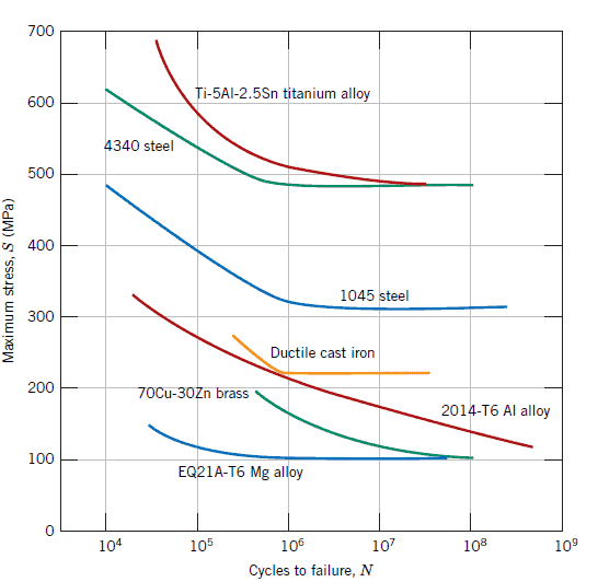
The American Society for Testing and Materials defines fatigue life, Nf, as the number of stress cycles of a specified character that a specimen sustains before failure of a specified nature occurs. Fatigue life is affected by cyclic stresses, residual stresses, material properties, internal defects, grain size, temperature, design geometry, surface quality, oxidation, corrosion, etc. For some materials, notably steel and titanium, there is a theoretical value for stress amplitude below which the material will not fail for any number of cycles, called a fatigue limit, endurance limit, or fatigue strength.
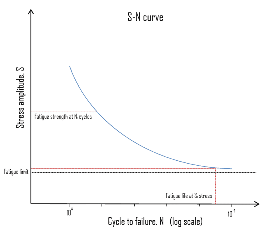
Engineers use several methods to determine a material’s fatigue life. One of the most useful is the stress-life method is commonly characterized by an S-N curve, also known as a Wöhler curve. This method is illustrated in the figure. It plots applied stress (S) against component life or the number of cycles to failure (N). As the stress decreases from some high value, component life increases slowly at first and then rapidly. Because fatigue like brittle fracture has such a variable nature, the data used to plot the curve will be treated statistically. The scatter in results is a consequence of the fatigue sensitivity to many tests and material parameters that are impossible to control precisely.
The following terms are defined for the S-N curve:
- Fatigue Limit. Fatigue (also called the endurance limit) is the stress level below which fatigue failure does not occur. This limit exists only for some ferrous (iron-based) and titanium alloys, for which the S–N curve becomes horizontal at higher N values. Other structural metals, such as aluminum and copper, do not have a distinct limit and will eventually fail even from small stress amplitudes. Typical values of the steel limit are 1/2 the ultimate tensile strength, to a maximum of 290 MPa (42 ksi).
- Fatigue Strength. The ASTM defines fatigue strength, SNf, as the value of stress at which failure occurs after some specified number of cycles (e.g., 107 cycles). For example, the fatigue strength for annealed Ti-6Al-4V titanium alloy is about 240 MPa at 107 cycles, and the stress concentration factor = 3.3.
- Fatigue Life. Fatigue life characterizes a material’s fatigue behavior. It is the number of cycles to cause failure at a specified stress level, as taken from the S–N plot.
The process of fatigue failure is characterized by three distinct steps:
- Crack initiation, a small crack forms at some point of high-stress concentration.
- Crack propagation, during which this crack advances incrementally with each stress cycle. Most of the fatigue life is generally consumed in the crack growth phase.
- Ultimate failure occurs rapidly once the advancing crack has reached a critical size.
Cracks associated with fatigue failure almost always initiate (or nucleate) the surface of a component at some point of stress concentration. Anything which leads to stress concentration, and the development of cracks, will reduce fatigue life. Therefore, increasing the degree of surface finish, polishing compared to grinding, improves fatigue life. Increasing the strength and hardness of the surface layers of metal components will also improve fatigue life.