 Welding is one of the most common joining processes. Two or more metal parts are joined to form a single piece by using high heat to melt the parts and allow them to cool, causing fusion. Although this concept is easy to describe, it is not simple to effect. Surface roughness, impurities, fitting imperfections, and the varied properties of the materials being joined complicate the joining process. Both similar and dissimilar metals (heterogeneous welding) may be welded. The joining bond is metallurgical (involving some diffusion) rather than just mechanical, as with riveting and bolting. Although welding is considered a relatively new process, its origins can be traced to ancient times. Until the end of the 19th century, the only welding process was forge welding, which blacksmiths had used for millennia to join iron and steel by heating and hammering. Today, a variety of welding methods exist, including arc and gas welding, as well as brazing and soldering. However, portions of this description do not apply to brazing, soldering, and adhesive bonding.
Physics of Welding
The goal of the joining processes is to cause diverse pieces of material to become a unified whole. In the case of two pieces of metal, when the atoms at the edge of one piece come close enough to the atoms at the edge of another piece for interatomic attraction to develop, the two pieces become one.
There are two main categories for welding:
- Fusion welding. In fusion welding, two edges or surfaces to be joined are heated to the melting point, and, where necessary, the molten filler metal is added to fill the joint gap. The high-temperature phase transitions inherent to these processes create a heat-affected zone (HAZ) in the material. Fusion welds are created by the coalescence of molten base metals mixed with molten filler metals. Heat for melting is either developed at the intended weld joint or applied to the intended joint from an external source. An example of a means of developing heat at the weld joint is the passing of current through the electrical contact resistance between the contacting surfaces of the materials to be welded. Most fusion welding processes apply heat from an external source to the weld joint to produce the weld bond. Heat is transported from the heat source to the joint by conduction, convection, and radiation. External heat sources include electron beams, laser beams, exothermic chemical reactions (used in oxyfuel gas welding and thermite welding), and electric arcs. Electric arcs, the most widely used heat source, are the basis for the various arc welding processes. Fusion welding manufactures many everyday items, including airplanes, cars, and structures.
- Solid-state welding. Two clean, solid metal surfaces are brought into sufficiently close contact for a metallic bond to be formed for solid phase welding. Solid phase welding can be accomplished at temperatures as low as room temperature. The bonding process is based either on deformation or diffusion and limited deformation, so atomic movement (diffusion) creates new bonds between atoms of two surfaces. Forge welding is a solid-state welding technique known for centuries. Many metals can be forged and welded, the most common being high and low-carbon steel. One of the most popular, ultrasonic welding, is used to connect thin sheets or wires made of metal or thermoplastic by vibrating them at high frequency and under high pressure. Another common process, explosion welding, involves joining materials by pushing them together under extremely high pressure. The energy from the impact plasticizes the materials, forming a weld, even though only a limited amount of heat is generated.
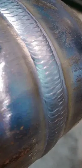
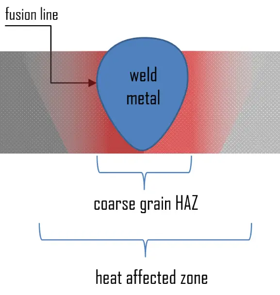 This section will focus on fusion welding, which is more common than solid-state welding. Fusion welding manufactures many everyday items, including airplanes, cars, and structures. Using a heat source with sufficient power makes it possible to fuse through a complete section of a very thick plate. The weld pool produced is difficult to control, and the heat-affected zone (HAZ) of such welds has a relatively coarse grain, adversely affecting the mechanical properties of the steel. The heat-affected zone (HAZ) is a ring surrounding the weld in which the temperature of the welding process, combined with the stresses of uneven heating and cooling, alters the heat-treatment properties of the alloy. The effects of welding on the material surrounding the weld can be detrimental—depending on the materials used and the heat input of the welding process used. The HAZ can be of varying size and strength. In the weld pool, heat is transported using convection and conduction.
An understanding of heat transfer is important in producing welds since the properties of a weldment are controlled by its geometry and by the composition and structure of the materials being welded.
Types of Welding Processes
The major categories of welding are briefly introduced in the next sections.
Arc Welding
Arc welding processes use a welding power supply to create and maintain an electric arc between an electrode and the base material to melt metals at the welding point. The intense heat produced by the arc quickly melts a portion of the base metal, forming a weld. This electrical arc is around 3590°C in its center. Filler metal is added in most welding processes to increase the volume and strength of the weld joint. A pool of molten metal, consisting of base and filler metal, is formed near the tip of the electrode. As the electrode is moved along the joint, the molten metal solidifies in its wake.
The welding power supply can use either direct current (DC), alternating current (AC), and consumable or non-consumable electrodes. The welding region is sometimes protected by inert or semi-inert gas, a shielding gas. In arc welding, the arc length is directly related to the voltage, and the amount of heat input is related to the current. The voltage supplied by power companies for industrial purposes-120 volts (V), 230 V, 380 V, or 480 V is too high for arc welding. Therefore, the first function of an arc welding power source is to reduce the high input or line voltage to a suitable output voltage range, 20 V to 80 V. Constant current power supplies are most often used for manual welding processes such as gas tungsten arc welding and shielded metal arc welding because they maintain a relatively constant current even as the voltage varies. This is important because, in manual welding, it can be difficult to hold the electrode perfectly steady, and as a result, the arc length and, thus, voltage tend to fluctuate.
Consumable – Inconsumable Electrode
An electrode rod can be either consumable or inconsumable. If the electrode is made of carbon or tungsten rod has the sole purpose of carrying current to sustain the electric arc between its tip and the workpiece. If a non-consumable electrode is used and the joint requires filler metal addition, then that metal must be supplied by a separately applied filler metal rod or wire. For a consumable electrode, the arc can be sustained by an electrode, which not only conducts the current for sustaining the arc but also melts and supplies filler metal to the joint.
Shielded Metal Arc Welding – SMAW
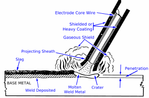
Shielded metal arc welding (SMAW) is one of the most common types of arc welding. It is also known as manual metal arc welding (MMAW) or stick welding. Shielded metal arc welding (SMAW) uses an electrode consisting of a filler metal rod coated with flux that protects the weld area from oxidation and contamination by producing carbon dioxide (CO2) gas during the welding process. The filler metal used in the rods must be compatible with the metal to be welded. The composition is usually close to that of the base metal. Electric current strikes an arc between the base material and the consumable electrode rod.
The SMAW process is the simplest in terms of equipment requirements. It is versatile and can be performed with relatively inexpensive equipment, making it well suited to shop jobs and field work. An operator can become proficient with a modest amount of training and mastery with experience. Most new welders start as “stick welders” and develop the necessary skills through training and experience. Weld times are rather slow since the consumable electrodes must be frequently replaced and because slag, the residue from the flux, must be chipped away after welding.
Gas Metal Arc Welding – GMAW
Gas metal arc welding (GMAW), also known as metal inert gas or MIG welding, is an arc welding process in which the electrode is a consumable bare wire, and shielding is accomplished by flooding the arc with an inert gas. Metal inert gas (MIG) welding differs from the SMAW process in that its electrode is a bare solid wire continuously fed to the weld area and becomes the filler metal as it is consumed. In contrast, SMAW electrodes must be discarded when they reach a minimum length. Gas metal arc welding is widely used in semiautomatic, machine, and automated modes. The gas shield must provide full protection because even a small amount of entrained air can contaminate the weld deposit. Originally, only inert gases such as argon and helium were used for shielding. Today, carbon dioxide is also used and may be mixed with inert gases. Because GMAW is continuously wire fed, the electrode does not need replacing at regular intervals, such as in the case of SMAW, making this process suitable for automated welding.
A related process, flux-cored arc welding (FCAW), uses similar equipment but uses wire consisting of a steel electrode surrounding a powder-fill material. This cored wire is more expensive than the standard solid wire and can generate fumes and/or slag, but it permits even higher welding speed and greater metal penetration.
Gas Tungsten Arc Welding – TIG Welding
Gas tungsten arc welding, also known as tungsten inert gas (TIG) welding, is an arc welding process that uses a non-consumable tungsten electrode and an inert gas for arc shielding. The GTAW can be implemented with or without filler metal. When filler metal is used, it is added to the weld pool from a separate rod or wire. The typical shielding gases used are argon, helium, or a mixture of these gases. TIG welding is especially useful for welding thin materials. This method is characterized by a stable arc and high-quality welds. Still, it requires significant operator skill and can only be accomplished at relatively low speeds. Since the GTAW process is a very clean welding process, it can be used to weld reactive metals, such as titanium and zirconium, aluminum, and magnesium.
Submerged Arc Welding
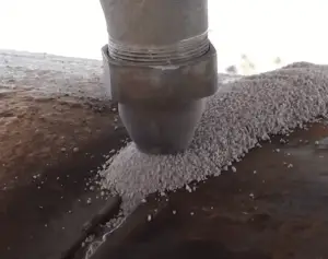 Submerged arc welding (SAW) is a high-quality welding method that involves submerging the welding arc beneath a mound of granular flux particles (consisting of lime, silica, manganese oxide, and calcium fluoride) as the arc is initiated. Additional flux is continually added in front of the electrode as weld travel progresses. The flux protects the arc and molten weld metal from the ambient atmosphere, thereby preventing the formation of oxides. Filler metal is obtained primarily from an electrode wire continuously fed through the blanket of flux into the arc and pool of molten flux. This increases arc quality since the flux blocks contaminants in the atmosphere. Melted flux becomes slag, a waste material that must be removed after welding. During the submerged arc welding process, not all flux turns into slag. Depending on the welding process, 50% to 90% of the flux can be reused.
Submerged arc welding is normally operated in the automatic or mechanized mode. Submerged arc welding is ideally suited for any application involving long, continuous welds. The ability to readily weld thick plates, sometimes with simple joint configurations, makes SAW the method of choice for welding components of large and thick structural assemblies. For example, a reactor pressure vessel is cylindrical with a hemispherical bottom head and a flanged and gasketed upper head. The bottom head is welded to the cylindrical shell, which consists of several rings welded together by submerged arc welding with a narrow gap. Narrow gap welding offers two major benefits. It is an economical joint configuration with less weld volume to fill compared to other joint configurations. The automation-friendly joint welded with moderate parameter limits weld defects gives a high-quality weld.
Resistance Welding
 Resistance welding (ERW) is a welding process that involves generating heat from the flow of electrical current through the joined parts. Small pools of molten metal are formed at the weld area as a high current (1000–100,000 A) is passed through the metal. Electric resistance welding is widely used, for example, in manufacturing steel pipes and assembling bodies for automobiles. The vehicle manufacturing industry, among others, employs the resistance processes extensively in applications in which the product design specifies gauge thicknesses that are lapped. Fully automatic and robotic systems are used for many of these applications.
Commonly implemented resistance welding processes are:
- resistance spot welding (RSW),
- resistance seam welding (RSEW),
- resistance projection welding (RPW)
- resistance stud welding.
The main process variables associated with these resistance welding processes are welding current, welding time, electrode force or pressure, electrode material, and tip configuration. Resistance welding (RW) was invented in 1886 by Professor Elihu Thomson, and it is one of the simplest and most commonplace fusion welding processes.
Resistance Spot Welding – RSW
Resistance spot welding or spot welding is a welding process used to join two or more overlapping metal sheets, studs, projections, or other closely fitted surfaces in one or more spots. In this method, the joint is produced by the heat generated due to the resistance of workpieces to the flow of current and the application of pressure. The weld is limited to the spots on overlapped workpieces. Hence not continuous. The pointed copper electrodes conduct the welding current to the work spot and apply pressure to form the strong joint. These contacting surfaces are heated by a short-timed pulse of low-voltage, high-amperage current to form a fused nugget of weld metal. Small pools of molten metal are formed at the weld area as a high current (1000–100,000 A) is passed through the metal. When the current flow is stopped, the electrode pressure is maintained while the weld metal cools rapidly and solidifies. The electrodes are either precipitated strengthened copper-chromium and/or zirconium alloy and must be exchanged after a certain amount of welds.
The method’s advantages include efficient energy use, limited workpiece deformation, high production rates, easy automation, and no required filler materials. The principal disadvantage is the need to have accessibility to both sides of the workpiece as opposed to being able to make welds from one side only. The most commonly used welding methods for automotive applications include resistance spot welding (RSW). The vehicle manufacturing industry, among others, employs the resistance processes extensively in applications in which the product design specifies gauge thicknesses that are lapped. Fully automatic and robotic systems are used for many of these applications. On average, the conventional steel body of a car contains 4500 spot weld joints.
Resistance Seam Welding – RSEW
Resistance seam welding is a process similar to the spot welding process. Still, instead of pointed electrodes, wheel-shaped electrodes roll along and often feed the workpiece, making it possible to make long continuous welds. This produces a weld at the faying surfaces of two similar metals. The electrodes are often disc-shaped and rotate as the material passes between them. The seam may be a butt joint or an overlap joint and is usually an automated process. The joint is normally gastight or liquid-tight. A series of welds is made without retracting the electrode wheels or releasing the electrode force between spots, but the wheels may advance intermittently or continuously.
Like spot welding, seam welding relies on two electrodes, usually made from copper, to apply pressure and current. Seam welding produces an extremely durable weld because the joint is forged due to the heat and pressure applied. Seam welding commonly occurs when manufacturing round or rectangular steel tubing.
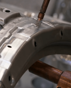
Laser Beam Welding
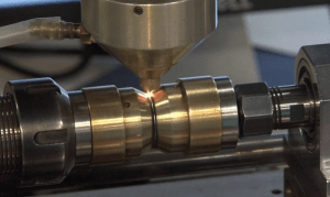 Laser beam welding is one of the high-power-density welding processes (on the order of 1 MW/cm2), which utilizes a very high rate of heat input. These processes usually require automation and have excellent potential for high-speed production. Laser beam welding affects the fusion welding of materials with the heat supplied by a laser beam impinges on the joint. A laser is a device that emits light through optical amplification based on the stimulated emission of electromagnetic radiation. For welding purposes, the laser beam is coherent, monochromatic light in the infrared or ultraviolet frequency portion of the electromagnetic radiation spectrum. Therefore, the beam is invisible. Commercial carbon dioxide (CO2) lasers can emit hundreds of watts in a single spatial mode that can be concentrated in a tiny spot. This emission is in the thermal infrared at 10.6 µm; such lasers are regularly used in industry for cutting and welding. The minimally divergent raw beam is focused into a small spot to obtain the greatest power density.
Laser Beam Welding – Advantages and Disadvantages
The main benefits include flexibility and improved productivity with substantial maintenance and energy cost savings while producing a strong weld. Metal sheets with thicknesses of 0.2 to 6mm can easily be laser welded. Most automotive industries employ cross-flow CO2 laser systems in the power range of 3 to 5 kW. Special caution must be taken for personal safety, and a safety enclosure is mandatory for protection against scattered radiation. The appropriate protective eyewear and clothing for the given type of laser must be used. Laser equipment is highly sophisticated and expensive, requiring knowledgeable personnel to install it and set parameters. Therefore this process requires automation and has excellent potential for high-speed production.
Oxyfuel Gas Welding
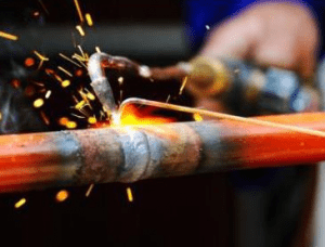 Gas welding utilizes the heat produced by a gas flame to melt the filler metal, if used, and the base metal, thereby creating a weld. Gas welding is one of the oldest and most versatile welding processes, but it has become less popular in industrial applications in recent years. It is still widely used for welding pipes and tubes and repair work. A similar process, called oxyfuel cutting, is used to cut metals.
The most common gas welding process is oxyacetylene welding. The equipment is relatively inexpensive and simple, generally employing the combustion of acetylene in oxygen to produce a welding flame temperature of about 3100 °C. Pure oxygen, instead of air, is used to increase the flame temperature to allow localized melting of the workpiece material. The temperature at which it burns is a function of the amount of oxygen present in the gas mixture.
Gases for Oxyfuel Welding
Common gases are:
- Acetylene – Oxygen. Compared with other fuel gases, oxyacetylene can produce the hottest and most concentrated flame. The oxyacetylene flame also produces carbon dioxide, a shielding gas. An oxyacetylene flame burns at about 3,773 K (3,500 °C; 6,332 °F). As a fuel, acetylene’s primary disadvantage, compared to other fuels, is its high cost.
- Stabilized methylacetylene-propadiene (MPS) has the storage and shipping characteristics of LPG and has a heat value a little lower than that of acetylene. MPS is recommended for cutting applications in particular rather than welding applications.
- Hydrogen – Oxygen. Hydrogen has a clean flame and is good for use on aluminium. It can be used at a higher pressure than acetylene and is, therefore, useful for underwater welding and cutting. It is a good type of flame when heating large amounts of material. Hydrogen is not used for welding steels and other ferrous materials because it causes hydrogen embrittlement. Oxyhydrogen flame burns at 3,073 K (2,800 °C; 5,072 °F).
Oxidizing – Neutral – Reducing Flames
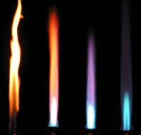
The temperature at which it burns is a function of the amount of oxygen present in the gas mixture. The figure demonstrates three types of flames that can be produced with oxyacetylene mixtures. Welding is generally carried out using the neutral flame setting with equal quantities of oxygen and acetylene.
- Reducing flame. The reducing flame is the flame with low oxygen and an excess of acetylene. Flame has a secondary feather extending from the inner cone. This secondary feather is caused by excess acetylene in the flame mixture, which alters the chemical composition of the weld pool by reducing iron oxide (reducing effect) and adding carbon (carburizing effect). It has a yellow or yellowish color due to carbon or hydrocarbons.
- Neutral flame. The neutral flame is the flame in which the amount of oxygen is precisely enough for burning, and neither oxidation nor reduction occurs. The flame is considered neutral because it neither significantly adds nor subtracts any elements from the weld pool. A flame with a good balance of oxygen is clear blue.
- Oxidizing flame. The oxidizing flame is the flame produced with an excessive amount of oxygen. When the amount of oxygen increases, the flame shortens, its color darkens, and it hisses and roars. Since, as its name suggests, it oxidizes the metal’s surface, this flame has a harmful effect on the properties of ferrous alloys. With some exceptions (e.g., platinum soldering in the jewelry), the oxidizing flame is usually undesirable for welding and soldering.
Friction Welding
Friction welding is a form of solid-state welding where the heat is obtained from the mechanically induced sliding motion between the parts to be welded. In solid-state welding, the joint is produced by applying pressure without significant melting of any of the work parts. Because no melting occurs, friction welding is not a fusion welding process in the traditional sense. The weld parts are held together under pressure. Generally, the frictional heat is generated by rotating one part against the other. When a certain temperature is reached, the rotational motion is seized, and the pressure applied welds the parts together. The bonding process is based either on deformation or diffusion and limited deformation, so atomic movement (diffusion) creates new bonds between atoms of two surfaces. The time required to generate friction welds is measured in seconds.
Friction Welding – Advantages and Disadvantages
The combination of fast joining times (on a few seconds) and direct heat input at the weld interface yields relatively small heat-affected zones. If automatic loading and unloading devices are installed, the machines are completely automatic. Shielding gas, flux, and filler metal need not be used. This process successfully joins a wide range of similar materials and many dissimilar metals, including aluminum and steel. This is particularly useful in aerospace, which combines lightweight aluminum stock with high-strength steel.
On the other hand, the workpiece has its dimensional limitations. FRW is restricted mostly to round bars with similar cross-sections, pieces of other forms are still possible to wield, but it is much harder. Friction welding usually uses a specific rotary machine, which needs higher capital costs.
Explosion Welding
Explosion welding involves joining materials by pushing them under extremely high pressure, which is generated by a controlled detonation. The energy from the impact plasticizes the materials, forming a weld, even though only a limited amount of heat is generated. High-ductility metals that have a face-centered cubic arrangement of atoms and do not work to harden quickly are best suited to the process. These include aluminum, copper, stainless steel, gold, silver, and platinum. Typical geometries produced include plates, tubing, and tube sheets. The process is commonly used for welding dissimilar materials, including bonding aluminum to carbon steel in ship hulls and stainless steel or titanium to carbon steel in petrochemical pressure vessels. A disadvantage of this method is that extensive knowledge of explosives is needed before the procedure may be attempted safely.