Photomultiplier tubes (PMTs) are photon detection device that uses the photoelectric effect combined with secondary emission to convert light into an electrical signal. A photomultiplier absorbs light emitted by the scintillator and re-emits it in the form of electrons via the photoelectric effect. The PMT has been the main choice for photon detection ever since because they have high quantum efficiency and high amplification.
The Photomultiplier tube is a key part of a scintillation detector. In general, a scintillation detector consists of:
- Scintillator. A scintillator generates photons in response to incident radiation.
- Photodetector. A sensitive photodetector (usually a photomultiplier tube (PMT), a charge-coupled device (CCD) camera, or a photodiode) converts the light to an electrical signal, and electronics process this signal.
Components of Photomultiplier Tube
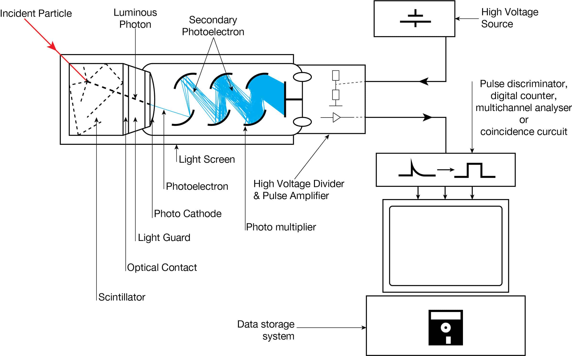
The device consists of several components, and these components are shown in the figure.
- Photocathode. Right after a thin entry window is a photocathode made of material in which the valence electrons are weakly bound and have a high cross-section for converting photons to electrons via the photoelectric effect. For example, Cs3Sb (cesium-antimony) may be used. As a result, the light created in the scintillator strikes the photocathode of a photomultiplier tube, releasing at most one photoelectron per photon.
- Dynodes. Using a voltage potential, this group of primary electrons is electrostatically accelerated and focused so that they strike the first dynode with enough energy to release additional electrons. There is a series (“stages”) of dynodes made of relatively low work function material. These electrodes are operated at increasing potential (e.g., ~100-200 V between dynodes). At the dynode, the electrons are multiplied by secondary emission. The next dynode has a higher voltage which makes the electrons released from the first accelerate towards it. At each dynode, 3-4 electrons are released for every incident electron, and with 6 to 14 dynodes, the total gain, or electron amplification factor, will be in the range of ~104-107 when they reach the anode. Typical operating voltages are in the range of 500 to 3000 V. At the final dynode, and sufficient electrons are available to produce a pulse of sufficient magnitude for further amplification. This pulse carries information about the energy of the original incident radiation, and the number of such pulses per unit of time also gives information about the intensity of the radiation.
Photomultiplier Tube – Principle of Operation
The operation of scintillation counters and photomultiplier tubes is summarized in the following points:
-
Scintillation Counter-Principle of Operation. Source: wikipedia.org License: Public Domain Ionizing radiation enters the scintillator and interacts with the scintillator material, and this causes electrons to be raised to an excited state.
- For charged particles, the track is the path of the particle itself.
- For gamma rays (uncharged), their energy is converted to an energetic electron via either the photoelectric effect, Compton scattering, or pair production.
- The excited atoms of the scintillator material de-excite and rapidly emit a photon in the visible (or near-visible) light range. The quantity is proportional to the energy deposited by the ionizing particle, and the material is said to fluoresce.
- Three classes of phosphors are used:
- inorganic crystals,
- organic crystals,
- plastic phosphors.
- The light created in the scintillator strikes the photocathode of a photomultiplier tube, releasing at most one photoelectron per photon.
- Using a voltage potential, this group of primary electrons is electrostatically accelerated and focused so that they strike the first dynode with enough energy to release additional electrons.
- These secondary electrons are attracted and strike a second dynode releasing more electrons. This process occurs in the photomultiplier tube.
- Each subsequent dynode impact releases further electrons, so there is a current amplifying effect at each dynode stage. Each stage is at a higher potential than the previous to provide the accelerating field.
- The primary signal is multiplied, and this amplification continues through 10 to 12 stages.
- At the final dynode, sufficient electrons are available to produce a pulse of sufficient magnitude for further amplification. This pulse carries information about the energy of the original incident radiation, and the number of such pulses per unit of time also gives information about the intensity of the radiation.

Quantum Efficiency
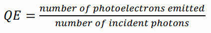
The sensitivity of a photocathode is usually quoted in terms of quantum efficiency. In general, the term quantum efficiency (QE) may apply to the incident photon to converted electron (IPCE) ratio of a photosensitive device. The quantum efficiency of the photocathode is defined as the probability for the conversion of incident photons to an electrical signal and is defined as:
The quantum efficiency of any photosensitive device is a strong function of the wavelength of the incident light, and an effort is made to match the spectral response of the photocathode to the emission spectrum of the scintillator in use. In the photomultiplier tube, the quantum efficiency is limited to 20-30%, but an average quantum efficiency over the emission spectrum of a typical scintillator is about 15-20%.
The standard for quotation is the number of photoelectrons per keV energy loss by fast electrons in a NaI(Tl) scintillator. About 8 ~ 10 photoelectrons are produced per keV energy loss for the peak quantum efficiency. Therefore, the average energy loss required to create a single photoelectron is ~ 100 eV, much bigger than the values in gas-filled or semiconductor detectors.
The PMT has been the main choice for photon detection ever since because they have high quantum efficiency and high amplification. Lately, however, semiconductors have begun to compete with the PMT. The photodiode, for example, has higher quantum efficiency in the visible range and above, lower power consumption, and smaller size. The quantum efficiency for the photodiode is high (60-80%) compared to the PMT (20-30%), which gives a higher energy resolution.