Today, the Rankine cycle is the fundamental operating cycle of all thermal power plants where an operating fluid is continuously evaporated and condensed.
In general, thermodynamics is the science that deals with energy production, storage, transfer, and conversion. Our goal here will be to introduce thermodynamics as the energy conversion science. At present, fossil fuel is still the world’s predominant energy source. But the burning of fossil fuels generates only thermal energy. Therefore these energy sources are so-called “primary energy sources” that must be converted to the secondary energy source, so-called energy carriers (electrical energy, etc.). A heat engine must be used to convert thermal energy into another form of energy.
Many heat engines operate in a cyclic manner, adding energy in the form of heat in one part of the cycle and using that energy to do useful work in another part of the cycle.
A process that eventually returns a system to its initial state is called a cyclic process. At the conclusion of a cycle, all the properties have the same value they had initially. A typical thermodynamic cycle consists of a series of thermodynamic processes transferring heat and work while varying pressure, temperature, and other state variables, eventually returning a system to its initial state.
The first law of thermodynamics dictates that the net heat input equals the network output over any cycle.
The increase in internal energy of a closed system is equal to the heat supplied to the system minus the work done by it.
∆Eint = Q – W
This is the First Law of Thermodynamics. It is the principle of conservation of energy, meaning that energy can neither be created nor destroyed but rather transformed into various forms as the fluid within the control volume is being studied.
It is the most important law for analyzing most systems and quantifying how thermal energy is transformed to other forms of energy.
The thermodynamic cycles can be divided into two primary classes:
- Power cycles. Power cycles are cycles that convert some heat input into mechanical work output. Thermodynamic power cycles are the basis for the operation of heat engines, which run the vast majority of motor vehicles and generate most of the world’s electric power.
- Heat pump cycles. Heat pump cycles transfer heat from low to high temperatures using mechanical work input. There is no difference between the thermodynamics of refrigerators and heat pumps. Both work by moving heat from a cold space to a warm space.
The following classification of thermodynamic cycles is made according to their constituent thermodynamic processes. In practice, simple idealized thermodynamic cycles are usually made out of four thermodynamic processes. In general, the following processes usually constitute thermodynamic cycles:
Carnot Cycle

See also: Carnot Cycle.
In 1824, a French engineer and physicist, Nicolas Léonard Sadi Carnot, advanced the study of the second law by forming a principle (also called Carnot’s rule) that specifies limits on the maximum efficiency any heat engine can obtain. In short, this principle states that the efficiency of a thermodynamic cycle depends solely on the difference between the hot and cold temperature reservoirs.
Carnot’s principle states:
- No engine can be more efficient than a reversible engine (Carnot heat engine) operating between the same high-temperature and low-temperature reservoirs.
- The efficiencies of all reversible engines (Carnot heat engines) operating between the same constant temperature reservoirs are the same, regardless of the working substance employed or the operation details.
The cycle of this engine is called the Carnot cycle. A system undergoing a Carnot cycle is called a Carnot heat engine. It is not an actual thermodynamic cycle but is a theoretical construct and cannot be built in practice. All real thermodynamic processes are somehow irreversible. They are not done infinitely slowly, and infinitesimally small steps in temperature are also theoretical fiction. Therefore, heat engines must have lower efficiencies than limits on their efficiency due to the inherent irreversibility of the heat engine cycle they use.
Otto Cycle
See also: Otto Cycle
See also: Atkinson Cycle
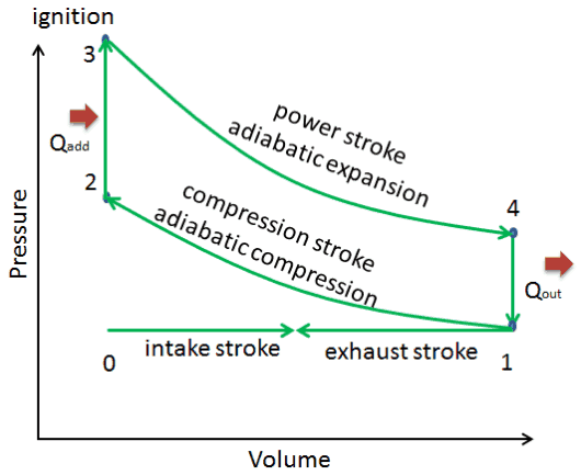
The cycle of the Otto engine is called the Otto cycle. It is one of the most common thermodynamic cycles found in automobile engines and describes the functioning of a typical spark ignition piston engine. In contrast to the Carnot cycle, the Otto cycle does not execute isothermal processes because these must be performed very slowly. In an ideal Otto cycle, the system executing the cycle undergoes a series of four internally reversible processes: two isentropic (reversible adiabatic) processes alternated with two isochoric processes.
Since Carnot’s principle states that no engine can be more efficient than a reversible engine (a Carnot heat engine) operating between the same high temperature and low-temperature reservoirs, the Otto engine must have lower efficiency than the Carnot efficiency. A typical gasoline automotive engine operates at around 25% to 30% of thermal efficiency. About 70-75% is rejected as waste heat without being converted into useful work, i.e., work delivered to wheels.
Diesel Cycle
See also: Diesel Cycle
See also: Dual Cycle
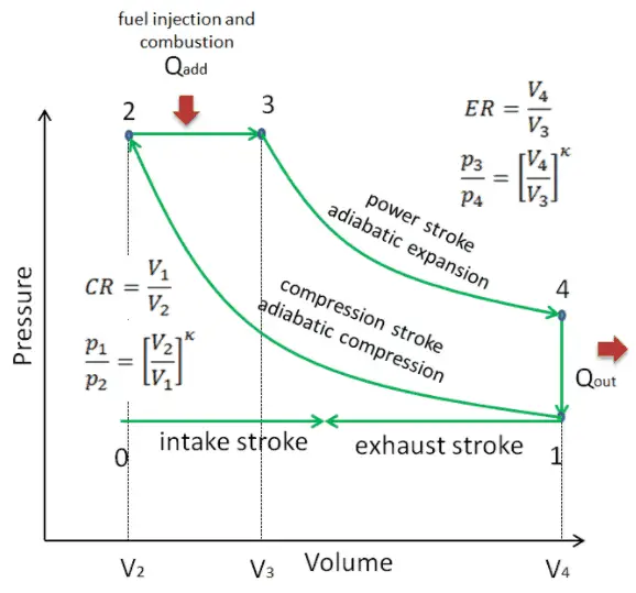
The diesel cycle is one of the most common thermodynamic cycles found in automobile engines and describes the functioning of a typical compression ignition piston engine. The Diesel engine is similar in operation to the gasoline engine. The most important difference is that:
- There is no fuel in the cylinder at the beginning of the compression stroke. Therefore autoignition does not occur in Diesel engines.
- A diesel engine uses compression ignition instead of spark ignition.
- Because of the high temperature developed during the adiabatic compression, the fuel spontaneously ignites as it is injected. Therefore no spark plugs are needed.
- Before the beginning of the power stroke, the injectors start to inject fuel directly into the combustion chamber. Therefore the first part of power stroke occurs approximately at the constant pressure.
- Higher compression ratios can be achieved in Diesel engines than in Otto engines
Brayton Cycle
See also: Brayton Cycle
See also: Ericsson Cycle
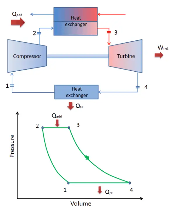
In 1872, an American engineer, George Bailey Brayton, advanced the study of heat engines by patenting a constant pressure internal combustion engine, initially using vaporized gas but later using liquid fuels such as kerosene. This heat engine is known as “Brayton’s Ready Motor”. The original Brayton engine used a piston compressor and piston expander instead of a gas turbine and gas compressor.
Today, modern gas turbine engines and airbreathing jet engines are also constant-pressure heat engines. Therefore we describe their thermodynamics by the Brayton cycle. In general, the Brayton cycle describes the workings of a constant-pressure heat engine.
It is one of the most common thermodynamic cycles found in gas turbine power plants or airplanes. In contrast to the Carnot cycle, the Brayton cycle does not execute isothermal processes because these must be performed very slowly. In an ideal Brayton cycle, the system executing the cycle undergoes a series of four processes: two isentropic (reversible adiabatic) processes alternated with two isobaric processes.
Rankine Cycle
See also: Rankine Cycle
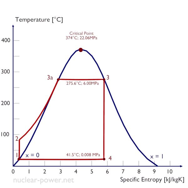
In 1859, a Scottish engineer, William John Macquorn Rankine, advanced the study of heat engines by publishing the “Manual of the Steam Engine and Other Prime Movers”. Rankine developed a complete theory of the steam engine and indeed of all heat engines. Together with Rudolf Clausius and William Thomson (Lord Kelvin), he contributed to thermodynamics, particularly focusing on the first of the three thermodynamic laws. The Rankine cycle was named after him and describes the performance of steam turbine systems, though the theoretical principle also applies to reciprocating engines such as steam locomotives. The Rankine cycle is an idealized thermodynamic cycle of a constant pressure heat engine that converts part of heat into mechanical work. In this cycle, the heat is supplied externally to a closed loop, which usually uses water (in a liquid and vapor phase) as the working fluid. In contrast to the Brayton cycle, the working fluid in the Rankine cycle undergo the phase change from a liquid to vapor phase and vice versa.
While many substances could be used as the working fluid in the Rankine cycle (inorganic or even organic), water is usually the fluid of choice due to its favorable properties, such as its non-toxic and unreactive chemistry, abundance, and low cost, as well as its thermodynamic properties. For example, water has the highest specific heat of any common substance – 4.19 kJ/kg K. Moreover it has a very high heat of vaporization, making it an effective coolant and medium in thermal power plants and other energy industries. In the case of the Rankine cycle, the Ideal Gas Law almost cannot be used (steam does not follow pV=nRT). Therefore all important parameters of water and steam are tabulated in so-called “Steam Tables “.
One of the major advantages of the Rankine cycle is that the compression process in the pump takes place on a liquid. By condensing the working steam to a liquid (inside a condenser), the pressure at the turbine outlet is lowered, and the energy required by the feed pump consumes only 1% to 3% of the turbine output power. These factors contribute to higher efficiency for the cycle.
Today, the Rankine cycle is the fundamental operating cycle of all thermal power plants where an operating fluid is continuously evaporated and condensed. It is one of the most common thermodynamic cycles because the turbine is steam-driven in most places in the world.