Brayton Cycle – Turbine Engine
In 1872, an American engineer, George Bailey Brayton, advanced the study of heat engines by patenting a constant pressure internal combustion engine, initially using vaporized gas but later using liquid fuels such as kerosene. This heat engine is known as “Brayton’s Ready Motor”. The original Brayton engine used a piston compressor and piston expander instead of a gas turbine and gas compressor.
Today, modern gas turbine engines and airbreathing jet engines are also constant-pressure heat engines. Therefore we describe their thermodynamics by the Brayton cycle. In general, the Brayton cycle describes the workings of a constant-pressure heat engine.
It is one of the most common thermodynamic cycles found in gas turbine power plants or airplanes. In contrast to the Carnot cycle, the Brayton cycle does not execute isothermal processes because these must be performed very slowly. In an ideal Brayton cycle, the system executing the cycle undergoes a series of four processes: two isentropic (reversible adiabatic) processes alternated with two isobaric processes.
Since Carnot’s principle states that no engine can be more efficient than a reversible engine (a Carnot heat engine) operating between the same high temperature and low-temperature reservoirs, a gas turbine based on the Brayton cycle must have lower efficiency than the Carnot efficiency.
A large single-cycle gas turbine typically produces for example 300 megawatts of electric power and has 35–40% thermal efficiency. Modern Combined Cycle Gas Turbine (CCGT) plants, in which the thermodynamic cycle of consists of two power plant cycles (e.g., the Brayton cycle and the Rankine cycle), can achieve a thermal efficiency of around 55%.
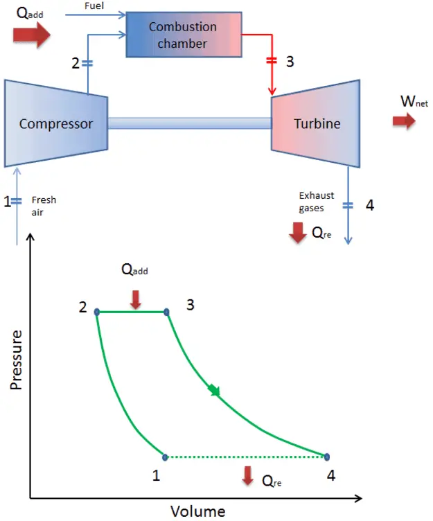
Brayton Cycle – Processes
Brayton Cycle – Processes
In a closed ideal Brayton cycle, the system executing the cycle undergoes a series of four processes: two isentropic (reversible adiabatic) processes alternated with two isobaric processes:
-
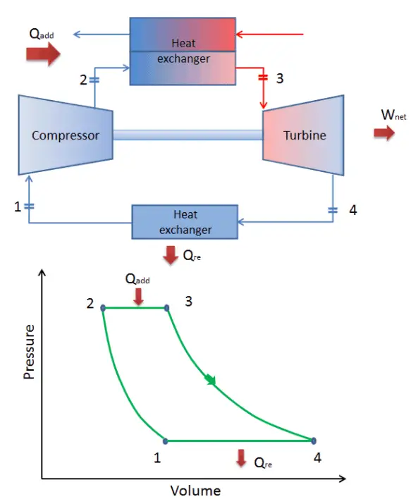
closed Brayton cycle Isentropic compression (compression in a compressor) – The working gas (e.g.,, helium) is compressed adiabatically from state 1 to state 2 by the compressor (usually an axial-flow compressor). The surroundings work on the gas, increasing its internal energy (temperature) and compressing it (increasing its pressure). On the other hand, the entropy remains unchanged. The work required for the compressor is given by WC = H2 – H1.
- Isobaric heat addition (in a heat exchanger) – In this phase (between state 2 and state 3), there is a constant-pressure heat transfer to the gas from an external source since the chamber is open to flow in out. In an open ideal Brayton cycle, the compressed air runs through a combustion chamber, burning fuel, and air or another medium is heated (2 → 3). It is a constant-pressure process since the chamber is open to flow in and out. The net heat added is given by Qadd = H3 – H2
- Isentropic expansion (expansion in a turbine) – The compressed and heated gas expands adiabatically from state 3 to state 4 in a turbine. The gas works on the surroundings (blades of the turbine) and loses an amount of internal energy equal to the work that leaves the system. The work done by the turbine is given by WT = H4 – H3. Again the entropy remains unchanged.
- Isobaric heat rejection (in a heat exchanger) – In this phase, the cycle completes by a constant-pressure process in which heat is rejected from the gas. The working gas temperature drops from point 4 to point 1. The net heat rejected is given by Qre = H4 – H1

During a Brayton cycle, the compressor works on the gas between states 1 and 2 (isentropic compression). Work is done by the gas in the turbine between stages 3 and 4 (isentropic expansion). The difference between the work done by the gas and the work done on the gas is the network produced by the cycle, and it corresponds to the area enclosed by the cycle curve (in the pV diagram).
As can be seen, it is convenient to use enthalpy or specific enthalpy and express the first law in terms of enthalpy in the analysis of this thermodynamic cycle. This form of the law simplifies the description of energy transfer. At constant pressure, the enthalpy change equals the energy transferred from the environment through heating:
Isobaric process (Vdp = 0):
dH = dQ → Q = H2 – H1
At constant entropy, i.e., in isentropic process, the enthalpy change equals the flow process work done on or by the system:
Isentropic process (dQ = 0):
dH = Vdp → W = H2 – H1
See also: Why power engineers use enthalpy? Answer: dH = dQ + Vdp
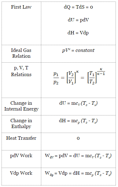
Isentropic Process
An isentropic process is a thermodynamic process in which the entropy of the fluid or gas remains constant. It means the isentropic process is a special case of an adiabatic process in which there is no transfer of heat or matter. It is a reversible adiabatic process. The assumption of no heat transfer is very important since we can use the adiabatic approximation only in very rapid processes.
Isentropic Process and the First Law
For a closed system, we can write the first law of thermodynamics in terms of enthalpy:
dH = dQ + Vdp
or
dH = TdS + Vdp
Isentropic process (dQ = 0):
dH = Vdp → W = H2 – H1 → H2 – H1 = Cp (T2 – T1) (for ideal gas)
Isentropic Process of the Ideal Gas
The isentropic process (a special case of the adiabatic process) can be expressed with the ideal gas law as:
pVκ = constant
or
p1V1κ = p2V2κ
in which κ = cp/cv is the ratio of the specific heats (or heat capacities) for the gas. One for constant pressure (cp) and one for constant volume (cv). Note that, this ratio κ = cp/cv is a factor in determining the speed of sound in a gas and other adiabatic processes.
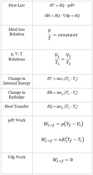
Isobaric Process
An isobaric process is a thermodynamic process in which the system’s pressure remains constant (p = const). The heat transfer into or out of the system does work and changes the system’s internal energy.
Since there are changes in internal energy (dU) and changes in system volume (∆V), engineers often use the enthalpy of the system, which is defined as:
H = U + pV
Isobaric Process and the First Law
The classical form of the first law of thermodynamics is the following equation:
dU = dQ – dW
In this equation, dW is equal to dW = pdV and is known as the boundary work. In an isobaric process and the ideal gas, part of the heat added to the system will be used to do work, and part of the heat added will increase the internal energy (increase the temperature). Therefore it is convenient to use enthalpy instead of internal energy.
Isobaric process (Vdp = 0):
dH = dQ → Q = H2– H1
At constant entropy, i.e., in the isentropic process, the enthalpy change equals the flow process work done on or by the system.
Isobaric Process of the Ideal Gas
The isobaric process can be expressed with the ideal gas law as:
or

On a p-V diagram, the process occurs along a horizontal line (called an isobar) with the equation p = constant.
See also: Charles’s Law