Reheat, Inter-cooling and Regeneration in Brayton Cycle
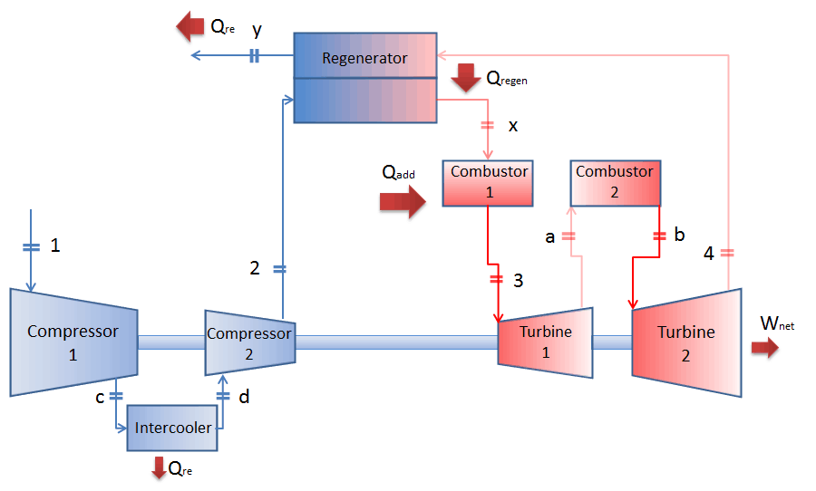
As was discussed, reheat and inter-cooling are complementary to heat regeneration. By themselves, they would not necessarily increase the thermal efficiency, however, when inter-cooling or reheat is used in conjunction with heat regeneration, a significant increase in thermal efficiency can be achieved, and the net work output is also increased. This requires a gas turbine with two stages of compression and two turbine stages.

The second Ericsson cycle is similar to the Brayton cycle but uses external heat and incorporates the multiple uses of an inter-cooling and reheat. It is like a Brayton cycle with an infinite number of reheat and intercooler stages in the cycle. Compared to the Brayton cycle, which uses adiabatic compression and expansion, an ideal Ericsson cycle consists of isothermal compression and expansion processes combined with isobaric heat regeneration. Applying inter-cooling, heat regeneration, and sequential combustion significantly increases the thermal efficiency of a turbine. The thermal efficiency of the ideal Ericsson cycle equals the Carnot efficiency.
Thermal Efficiency Improvement – Brayton Cycle
There are several methods, how can be the thermal efficiency of the Brayton cycle improved. Assuming that the maximum temperature is limited by metallurgical consideration, these methods are:
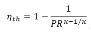
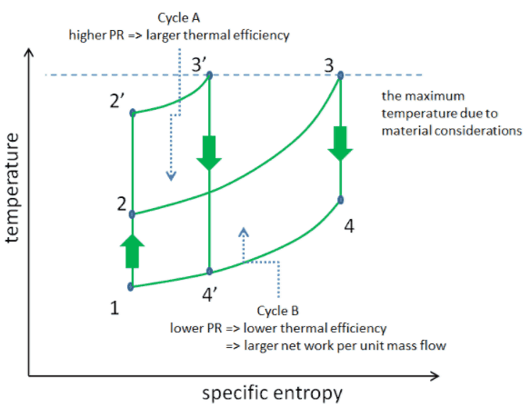
As was discussed, increasing the pressure ratio increases the compressor discharge temperature. Since the turbine inlet temperature is limited by the maximum temperature that the turbine blades can withstand, the pressure ratio influences the heat amount added to the flow. Moreover, with an increase in the pressure ratio, the diameter of the compressor blades becomes progressively smaller in higher pressure stages of the compressor. Because the gap between the blades and the engine casing increases in size as a percentage of the compressor blade height as the blades get smaller in diameter. A greater percentage of the compressed air can leak back past the blades in higher pressure stages. This causes a leak back, and as a result, it decreases the isentropic compressor efficiency (will be discussed later). Finally, from the formula for the thermal efficiency in terms of pressure ratio can be seen, there is a smaller gain as the pressure ratio increases (due to the exponent).
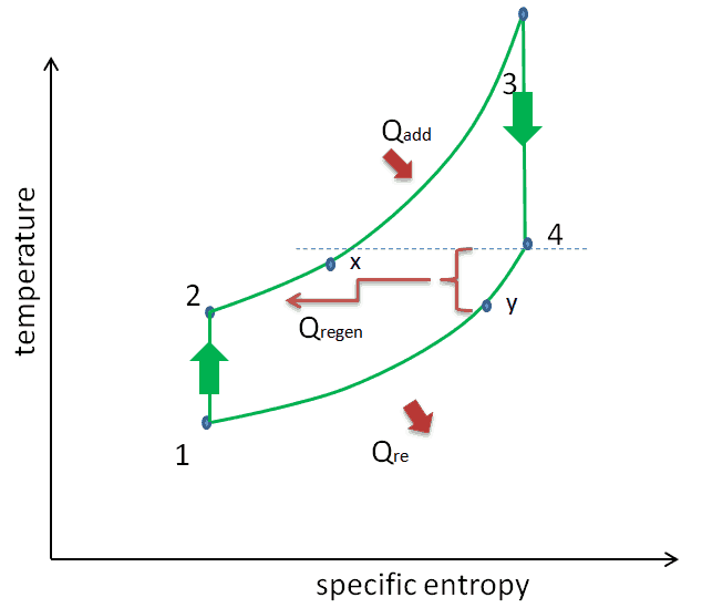
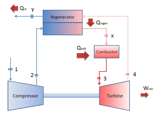
Significant increases in the thermal efficiency of gas turbine power plants can be achieved by reducing the amount of fuel that must be burned in the combustion chamber. This can be done by transferring heat from the turbine exhaust gas, which is normally well above the ambient temperature, to the compressor discharge air flow known as heat regeneration. Especially at a low or moderate pressure ratio, there is a high-temperature increase in the combustion chamber. The turbine exhaust gas might still contain a significant amount of heat at a higher temperature than the compressor outlet gas (after the last compression stage but before the combustor). For this purpose, a heat exchanger called a regenerator is used. Sometimes engineers use the term economizer, a heat exchanger intended to reduce energy consumption, especially in preheating a fluid.
This heat regenerator allows the air exiting the compressor to be preheated before entering the combustion chamber, reducing the amount of fuel that must be burned in the combustor. This form of heat recycling is only possible if the gas turbine is run with a low-pressure ratio.
As stated, the temperature difference between turbine and compressor outlets is crucial and determines the amount of heat that can be recovered. In case of negative difference (i.e., T2 > T4), heat regeneration is not possible. There are two main ways, how to change this difference:
- to increase the turbine outlet temperature (T4) through reheat of the flow during the expansion phase (i.e., use of a multi-stage turbine with a reheat combustor or with a reheater)
- to decrease the compressor outlet temperature (T2) through inter-cooling of the flow during the compression phase (i.e., use of a multi-stage compressor with an intercooler)
Therefore reheat, and inter-cooling are complementary with heat regeneration. By themselves, they would not necessarily increase the thermal efficiency. However, a significant increase in thermal efficiency can be achieved when inter-cooling or reheat is used in conjunction with heat regeneration.
It must be noted, transferring heat from the turbine outlet to the compressor inlet would reduce efficiency, as hotter inlet air means more volume, thus more work for the compressor. Engineers must also consider pressure losses generated by the heat exchanger that slightly reduce the power of the gas turbine.
Regeneration vs. Recuperation of Heat
In general, the heat exchangers used in regeneration may be classified as either regenerators or recuperators.
- A regenerator is a type of heat exchanger where heat from the hot fluid is intermittently stored in a thermal storage medium before it is transferred to the cold fluid. It has a single flow path in which the hot and cold fluids alternately pass through.
- A recuperator is a heat exchanger with separate flow paths for each fluid along its passages, and heat is transferred through the separating walls. Recuperators (e.g.,, economizers) are often used in power engineering to increase the overall efficiency of thermodynamic cycles, for example, in a gas turbine engine. The recuperator transfers some of the waste heat in the exhaust to the compressed air, thus preheating it before entering the combustion chamber. Many recuperators are designed as counterflow heat exchangers.

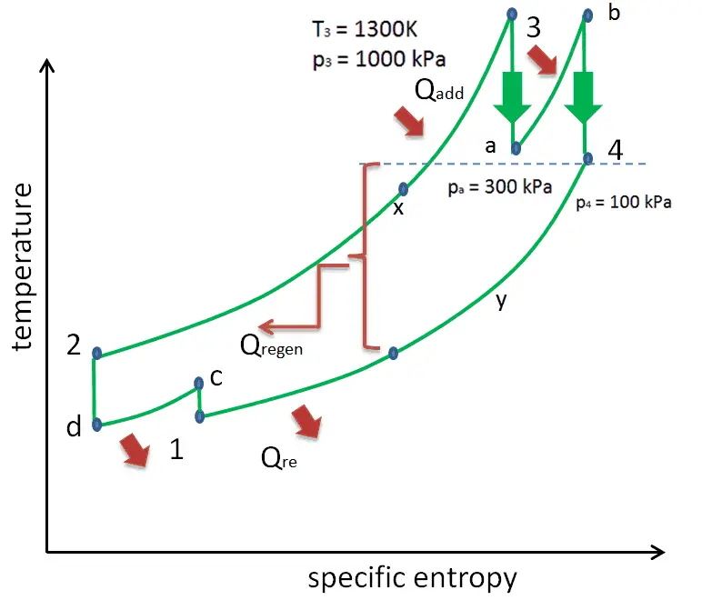
As discussed, the maximum temperature is limited by metallurgical consideration. Still, to deliver more heat at a temperature close to the peak of the cycle, the gas can be reheated in a reheater. This involves splitting the turbine, i.e., using a multi-stage turbine with a reheat combustor or a reheater. The turbine’s high pressure and low-pressure stages may be on the same shaft to drive a common generator, but they will have separate cases. With a reheater, the flow is extracted after a partial expansion (point a), run back through the heat exchanger to heat it back up to the peak temperature (point b), and then passed to the lower pressure stage of the turbine. The expansion is then completed in this stage from point b to point 4.
With this arrangement, the net work per unit of mass flow can be increased. Despite the increase in net work with reheat, the cycle thermal efficiency would not necessarily increase because a greater total heat addition would be required. On the other hand, the temperature at the exit of the turbine (low-pressure stage) is higher with reheat than without reheat, so there is the potential for heat regeneration. Therefore reheat, and regeneration is complementary. They are usually used together to increase the thermal efficiency of a gas turbine.

Significant increases in the thermal efficiency of gas turbine power plants can also be achieved through inter-cooling. Intercooling can be applied between compressor stages to reduce compression work, WC, hence increasing the overall power of the gas turbine.
For this purpose, a heat exchanger known as an intercooler is usually used between stages of a multi-stage compression process. In general, intercoolers are heat exchangers used in many applications, including air compressors, air conditioners, refrigerators, and gas turbines. Intercoolers are also widely known in automotive use as turbochargers or superchargers, but here they increase intake air charge density, hence the power of an engine.
In a gas turbine power plant, thermal efficiency is highly important, and inter-cooling with heat regeneration is widely used. This involves splitting the compressor, i.e., using a multi-stage compressor with an intercooler or intercoolers. The compressor’s high pressure and low-pressure stages may be on the same shaft, even with a turbine or a generator, but it is not a rule. With an intercooler, the flow is extracted after a partial compression (point c), run through the heat exchanger (intercooler) to cool it to the ambient temperature (point d), and then passed to the high stage of the compressor. The compression is then completed in the second compressor from point d to point 2.
With this arrangement, the net work per unit of mass flow (↑Wnet = WT – ↓WC) can be increased by reducing the compression work (↓WC). Despite the increase in net work with inter-cooling, the cycle thermal efficiency would not necessarily increase because the temperature of the air entering the combustor would be reduced, and a greater total heat addition would be required to achieve the desired turbine inlet temperature. On the other hand, the temperature at the exit of the compressor (high-pressure stage) is lower with inter-cooling than without inter-cooling, so there is the potential for heat regeneration (Qregen increases). Note that the heat regeneration requires a lower compressor outlet temperature than the turbine outlet temperature (simply due to the 2nd law). This temperature difference determines the amount of heat available for heat regeneration.
Therefore reheat, and inter-cooling are complementary with heat regeneration. By themselves, they would not necessarily increase the thermal efficiency. However, a significant increase in thermal efficiency can be achieved when inter-cooling or reheat is used in conjunction with heat regeneration.
Some large compressors with higher pressure ratios have several stages of compression with inter-cooling between stages. Engineers must also take into consideration pressure losses generated by all heat exchangers that slightly increase compression work. The certain gas turbine design (the number of intercoolers, reheaters, and regenerators) is an engineering problem and depends on the certain purpose of the gas turbine.