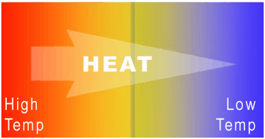
According to the second law of thermodynamics, many thermodynamic processes proceed naturally in one direction but not the opposite. For example, when a temperature difference does exist, heat flows spontaneously from the warmer system to the colder system, never the reverse. In fact, such heat flow (from a colder body to a warmer system) would not violate the first law of thermodynamics, i.e., energy would be conserved. But it doesn’t happen in nature.
Directions of thermodynamic processes are subject of the second law of thermodynamics, especially of the Clausius Statement of the Second Law, which states:
“It is impossible to construct a device which operates on a cycle and whose sole effect is the transfer of heat from a cooler body to a hotter body.”
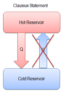 Heat cannot spontaneously flow from cold system to hot system without external work being performed on the system. This is exactly what refrigerators and heat pumps accomplish. In a refrigerator, heat pump, or air conditioner, heat flows from cold to hot, but only when forced by external work. These devices are driven by electric motors, requiring work from their surroundings to operate. There is no difference between the thermodynamics of refrigerators and heat pumps. Both work by moving heat from a cold space to a warm space.
See also: What is Temperature
See also: Heat in Thermodynamics
While internal energy refers to the total energy of all the molecules within the object, heat is the amount of energy flowing spontaneously from one body to another due to their temperature difference. Heat is a form of energy, but it is energy in transit. Heat is not a property of a system. However, the transfer of energy as heat occurs at the molecular level due to a temperature difference.
 Consider a metal block at high temperature that consists of atoms oscillating intensely around their average positions. At low temperatures, the atoms continue to oscillate but with less intensity. If a hotter block of metal is put in contact with a cooler block, the intensely oscillating atoms at the edge of the hotter block give off their kinetic energy to the less oscillating atoms at the edge of the cool block. In this case, there is energy transfer between these two blocks, and heat flows from the hotter to the cooler block by these random vibrations.
In general, when two objects are brought into thermal contact, heat will flow between them until they come into equilibrium with each other. When a temperature difference does exist, heat flows spontaneously from the warmer system to the colder system. Heat transfer occurs by conduction or by thermal radiation. When the flow of heat stops, they are said to be at the same temperature. They are then said to be in thermal equilibrium.
Heat Pump – Operating Principle
The term heat pump is usually reserved for a device that can heat a house in winter by using an electric motor that does work W to take heat Qcold from the outside at low temperature and delivers heat Qhot to the warmer inside of the house.
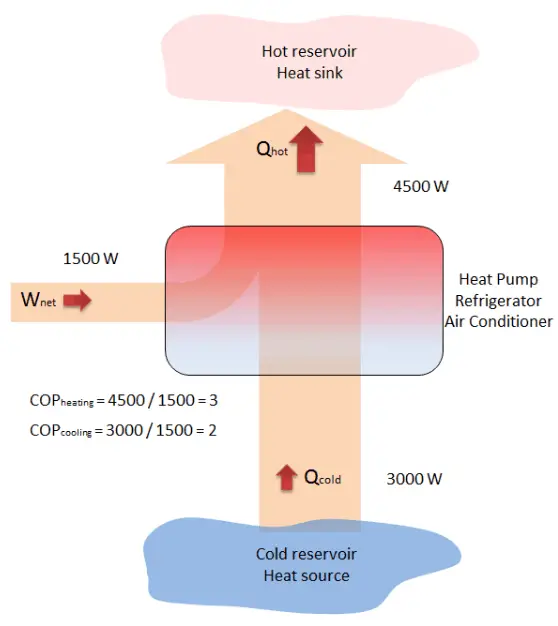
The operating principle of refrigerators, air conditioners, and heat pumps is the same, and it is just the reverse of a heat engine. In general, a heat pump is a device that transfers heat energy from a heat source to a “heat sink,” but in this case, the transfer occurs in the opposite direction of spontaneous heat transfer by absorbing heat from a cold space and releasing it to a warmer one. As diagrammed in the figure, by doing external work W, heat is taken from a low-temperature region (heat source), and a greater amount of heat is exhausted at a higher temperature (heat sink).
The most widely used thermodynamic cycle or method for heating, air-conditioning, refrigerators, and heat pumps is the vapor compression cycle.
Vapor-compression Cycle – Vapor-compression Refrigeration
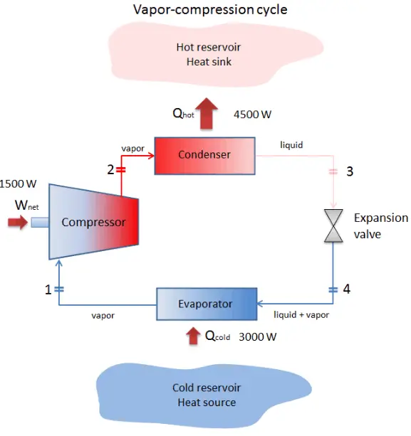
The vapor-compression uses a circulating liquid refrigerant as the medium (usually R134a), which absorbs and removes heat from the space to be cooled and subsequently rejects that heat elsewhere. The figure depicts a typical, single-stage vapor-compression system. The typical vapor-compression system consists of four components:
- Compressor
- Condenser
- Expansion valve (also called a throttle valve)
- Evaporator
In an ideal vapor-compression cycle, the system executing the cycle undergoes a series of four processes: one isentropic (reversible adiabatic) process, one throttling process alternated with two isobaric processes:
- Isentropic compression (compression in the piston compressor) – A circulating refrigerant such as R134a enters a compressor as low-pressure vapor at or slightly below the temperature of the refrigerator interior. The gaseous medium is compressed adiabatically from state 1 to state 2 by piston compressor (or by centrifugal pumps) to relatively high pressure and temperature. The surroundings do work on the gas, increasing its internal energy (temperature) and compressing it (increasing its pressure). On the other hand, the entropy remains unchanged. The work required for the compressor is given by WC = H2 – H1.
- Isobaric heat rejection (in a condenser) – The superheated vapor travels under pressure through coils or tubes that make up the condenser. In this phase, the refrigerant passes through the condenser, where the refrigerant condenses, and there is heat transfer from the refrigerant to the cooler surroundings. The net heat rejected is given by Qre = H3 – H2. As the refrigerant leaves the condenser, it is still under pressure but is now only slightly above room temperature.
- Isenthalpic process (expansion in an expansion valve) – The refrigerant at state 3 enters the expansion valve and expands to the evaporator pressure. This process is usually modeled as a throttling process for which enthalpy remains constant. H4 = H3. The sudden decrease in pressure results in explosive-like flash evaporation of a portion (typically about half) of the liquid. The latent heat absorbed by this flash evaporation is drawn mostly from the adjacent still-liquid refrigerant, a phenomenon known as auto-refrigeration.
- Isobaric heat addition (in an evaporator) – The cold and partially vaporized refrigerant continues through the coils or tubes of the evaporator unit. In this phase (between state 4 and state 1), there is a constant-pressure heat transfer to the liquid medium from an external source since the chamber is open to flow in and out. As the refrigerant passes through the evaporator, heat transfer from the refrigerated space results in the vaporization of the refrigerant. The net heat added is given by Qadd = H1 – H4
During a vapor-compression cycle, work is done on the fluid by the pumps between states 1 and 2 (isentropic compression). There is no work done by the fluid since between stages 3 and 4 the process is isenthalpic. The working fluid in a vapor-compression cycle follows a closed loop and is reused constantly.
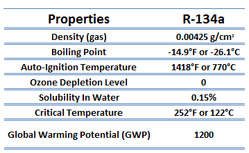
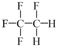 R134a, chemically 1,1,1,2-tetrafluoroethane (CF3CH2F) is a non-flammable gas used primarily as a “high-temperature” refrigerant for domestic refrigeration and automobile air conditioners. It is safe for normal handling as it is non-toxic, non-flammable, and non-corrosive. It is now being used as a replacement for the more environmentally harmful R-12 refrigerant in the area of centrifugal, rotary screw, scroll, and reciprocating compressors.
Reversible Heat Pumps
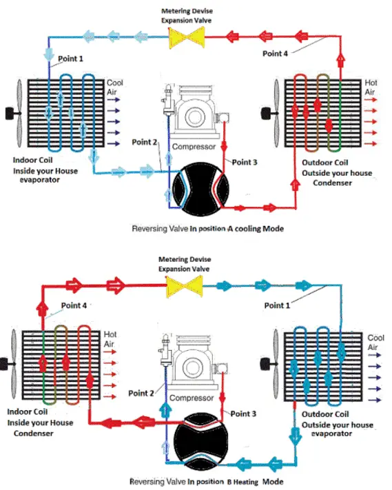 Reversible heat pumps work in either direction to provide heating or air conditioning (cooling) to the internal space. They employ a reversing valve to reverse the flow of refrigerant from the compressor through the condenser and evaporation coils.
Heating and Air Conditioning
In heating mode, heat pumps are three to four times more effective at heating (i.e., they can have COP = 4) than simple electrical resistance heaters using the same amount of electricity. Typically installed cost for a heat pump is about 20 times greater than for resistance heaters. In heating mode, the outdoor coil is an evaporator, while the indoor is a condenser.
In cooling mode, the flow is reversed, and the outdoor coil is a condenser, while the indoor is an evaporator. In heating mode, the outdoor coil is an evaporator, while the indoor is a condenser. The COP for cooling mode is less than for heating mode because the work done by the compressor is utilized only during the heating mode.
Coefficient of Performance – Heat Pump, Refrigerator, Air Conditioner
In general, the thermal efficiency, ηth, of any heat engine as the ratio of the work it does, W, to the heat input at the high temperature, QH.
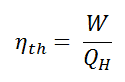
The thermal efficiency, ηth, represents the fraction of heat, QH, that is converted to work.
But in heat pumps and refrigerators, the work is not output. For refrigeration or heat pumps, thermal efficiency indicates the extent to which the energy added by work is converted to net heat output. From an economic point of view, the best refrigeration cycle is one that removes the greatest amount of heat from the inside of the refrigerator (cold reservoir) for the least expenditure of mechanical work or electric energy. The relevant ratio is, therefore, the larger this ratio, the better the refrigerator. We call this ratio the coefficient of performance, denoted by COP.
The coefficient of performance, COP, is also defined for heat pumps, but at this point, we follow the net heat added to the hot reservoir. The COP usually exceeds 1, especially in heat pumps, because, instead of just converting work to heat, it pumps additional heat from a heat source to where the heat is required.
In general, COP is highly dependent on operating conditions, especially absolute temperature and relative temperature between the heat sink and system.
Coefficient of Performance – Refrigerator, Air Conditioner
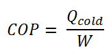
The coefficient of performance, COP, of a refrigerator is defined as the heat removed from the cold reservoir Qcold (i.e., inside a refrigerator) divided by the work W done to remove the heat (i.e., the work done by the compressor).
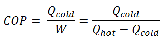
As can be seen, the better (more efficient) the refrigerator is when more heat Qcold can be removed from the inside of the refrigerator for a given amount of work. Since the first law of thermodynamics must be valid also in this case (Qcold + W = Qhot), we can rewrite the above equation:
For an ideal refrigerator (without losses and irreversibilities) can be derived that:

These formulas are also applied for an air conditioner, which works very much like a refrigerator.
On the other hand, the COP for heating and cooling is different.
Coefficient of Performance – Heat Pump
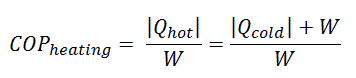
For heating, the COP is the ratio of the heat added to the system (hot reservoir). Using the first law of thermodynamics, define COP also as the heat removed from the cold reservoir plus the input work to the input work.
For an ideal heat pump (without losses and irreversibilities) can be derived that:
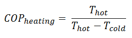
Note that these equations must use an absolute temperature scale (Tcold, Thot), and it is only a theoretical maximum efficiency. According to the above formula, the maximum achievable COP for Thot = 35 °C (308 K) and Tcold = 0 °C (273 K) would be 8.8. But in reality, the best systems are around 4.5.
As can be seen, the COP of a heat pump system can be improved by reducing the temperature difference (Thot – Tcold). Therefore, reducing the output temperature (Thot) is very efficient but requires very efficient heat transfer from the heat pump system to surroundings (i.e., use of piped floor). An increase in the input temperature (Tcold) means, for example, an oversized ground source of heat.
Example – Heat Pump – Heating and Air Conditioning
A reversible heat pump has a coefficient of performance COP = 3.0 when operated in the heating mode. Its compressor consumes 1500 W of electric energy.
- Calculate the amount of heat (Qhot) the heat pump can add to a room?
- If the heat pump were turned to the cooling mode (i.e., to act as an air conditioner in the summer), what would you expect its coefficient of performance to be? Assume all else stays the same and neglect all other losses.
Solution:
From the COP, which is defined as:
the amount of heat the heat pump can add to a room is equal to:
Qhot = COPheating x W = 3 x 1500 = 4500 W or 4500 J/s
In the case of the cooling mode, the heat pump (air conditioner) with a 1500 W motor can take heat Qcold from inside the house and then dump Qhot = 4500 W to the hot outside. Using the first law of thermodynamics, which states:
Qcold + W = Qhot,
we obtain the heat, Qcold = 3000 W. From the definition: COPcooling = 3000/1500 = 2.
Note that, in this example, we have many assumptions. For example, we assumed that the temperature difference (Thot – Tcold) is the same for both modes. But we have swapped reservoirs without any impact on COP. It is only an illustrative example.
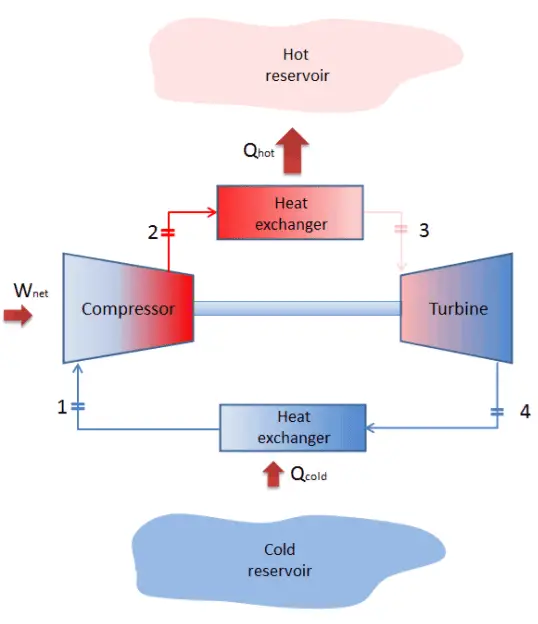
Reverse Brayton Cycle – Brayton Refrigeration Cycle
In general, the Brayton cycle describes the workings of a constant-pressure heat engine. Today, modern gas turbine engines and airbreathing jet engines are also constant-pressure heat engines.
A Brayton cycle that is driven in the reverse direction is known as the reverse Brayton cycle. Its purpose is to move heat from the colder to the hotter body rather than produce work. In compliance with the second law of thermodynamics, heat cannot spontaneously flow from cold system to hot system without external work being performed on the system. Heat can flow from colder to the hotter body, but only when forced by external work. This is exactly what refrigerators and heat pumps accomplish. These are driven by electric motors requiring work from their surroundings to operate. One of the possible cycles is a reverse Brayton cycle, which is similar to the ordinary Brayton cycle, but it is driven in reverse via net work input. This cycle is also known as the gas refrigeration cycle or the Bell Coleman cycle. This type of cycle is widely used in jet aircraft for air conditioning systems using air from the engine compressors. It is also widely used in the LNG industry, where the largest reverse Brayton cycle is for subcooling LNG using 86 MW of power from a gas turbine-driven compressor and nitrogen refrigerant.