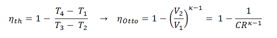
When we rewrite the expression for thermal efficiency using the compression ratio, we conclude the air-standard Otto cycle thermal efficiency is a function of compression ratio and κ = cp/cv.
Thermal Efficiency for Otto Cycle
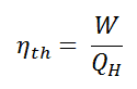
In general, the thermal efficiency, ηth, of any heat engine is defined as the ratio of the work it does, W, to the heat input at the high temperature, QH.
The thermal efficiency, ηth, represents the fraction of heat, QH, converted to work. Since energy is conserved according to the first law of thermodynamics and energy cannot be converted to work completely, the heat input, QH, must equal the work done, W, plus the heat that must be dissipated as waste heat QC into the environment. Therefore we can rewrite the formula for thermal efficiency as:

The heat absorbed occurs during combustion of fuel-air mixture, when the spark occurs, roughly at constant volume. Since during an isochoric process there is no work done by or on the system, the first law of thermodynamics dictates ∆U = ∆Q. Therefore, the heat added and rejected is given by:
Qadd = mcv (T3 – T2)
Qout = mcv (T4 – T1)
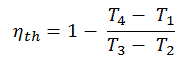
Substituting these expressions for the heat added and rejected in the expression for thermal efficiency yields:
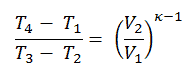
We can simplify the above expression using the fact that the processes 1 → 2 and from 3 → 4 are adiabatic, and for an adiabatic process, the following p,V,T formula is valid:
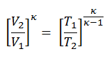
It can be derived that:
In this equation, the ratio V1/V2 is known as the compression ratio, CR. When we rewrite the expression for thermal efficiency using the compression ratio, we conclude the air-standard Otto cycle thermal efficiency is a function of compression ratio and κ = cp/cv.

It is a very useful conclusion because it is desirable to achieve a high compression ratio to extract more mechanical energy from a given mass of the air-fuel mixture. A higher compression ratio permits the same combustion temperature to be reached with less fuel while giving a longer expansion cycle. This creates more mechanical power output and lowers the exhaust temperature. Lowering the exhaust temperature causes the lowering of the energy rejected to the atmosphere. This relationship is shown in the figure for κ = 1.4, representing ambient air.
Compression Ratio – Otto Engine
The compression ratio, CR, is defined as the ratio of the volume at the bottom dead center and the volume at the top dead center. It is a key characteristic of many internal combustion engines. In the following section, it will be shown that the compression ratio determines the thermal efficiency of the used thermodynamic cycle of the combustion engine. It is desired to have a high compression ratio because it allows an engine to reach higher thermal efficiency.
For example, let assume an Otto cycle with compression ratio of CR = 10 : 1. The volume of the chamber is 500 cm³ = 500×10-6 m3 (0.5l) prior to the compression stroke. For this engine all required volumes are known:
- V1 = V4 = Vmax = 500×10-6 m3 (0.5l)
- V2 = V3 = Vmin = Vmax / CR = 55.56 ×10⁻⁶ m3
Note that (Vmax – Vmin) x number of cylinders = total engine displacement.
Examples of Compression Ratios – Gasoline vs. Diesel
- The compression ratio in a gasoline-powered engine will usually not be much higher than 10:1 due to potential engine knocking (autoignition) and not lower than 6:1.
- A turbocharged Subaru Impreza WRX has a compression ratio of 8.0:1. In general, turbocharged or supercharged engines already have compressed air at the air intake. Therefore they are usually built with a lower compression ratio.
- A stock Honda S2000 engine (F22C1) has a compression ratio of 11.1:1.
- Some atmospheric sportscar engines can have a compression ratio up to 12.5 : 1 (e.g.,, Ferrari 458 Italia).
- In 2012, Mazda released new petrol engines under the brand name SkyActiv with a 14:1 compression ratio. Residual gas is reduced by using 4-2-1 engine exhaust systems, implementing a piston cavity, and optimizing fuel injection to reduce the risk of engine knocking.
- The Diesel engines have a compression ratio that normally exceeds 14:1, and ratios over 22:1 are also common.