There is not enough time for energy transfer as heat to take place to or from the system in these rapid processes.
In real devices (such as turbines, pumps, and compressors), heat losses and losses in the combustion process occur. Still, these losses are usually low compared to overall energy flow, and we can approximate some thermodynamic processes by the adiabatic process.
Adiabatic Process and the First Law
For a closed system, we can write the first law of thermodynamics in terms of enthalpy:
dH = dQ + Vdp
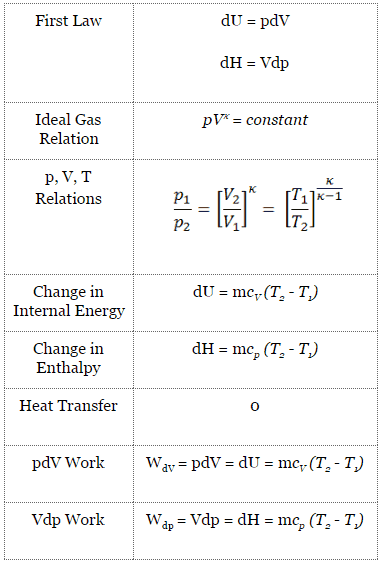
In this equation, the term Vdp is a flow process work. This work, Vdp, is used for open flow systems like a turbine or a pump in which there is a “dp”, i.e., change in pressure. As can be seen, this form of the law simplifies the description of energy transfer. In an adiabatic process, the enthalpy change equals the flow process work done on or by the system:
Adiabatic process (dQ = 0):
dH = Vdp → W = H2 – H1 → H2 – H1 = Cp (T2 – T1) (for an ideal gas)
See also: First Law of Thermodynamics
See also: Ideal Gas Law
See also: What is Enthalpy
Adiabatic Expansion – Adiabatic Compression
See also: What is an Ideal Gas
In an ideal gas, molecules have no volume and do not interact. According to the ideal gas law, pressure varies linearly with temperature and quantity and inversely with volume.
pV = nRT
where:
- p is the absolute pressure of the gas
- n is the amount of substance
- T is the absolute temperature
- V is the volume
- R is the ideal, or universal, gas constant, equal to the product of the Boltzmann constant and the Avogadro constant,
In this equation, the symbol R is a constant called the universal gas constant that has the same value for all gases—namely, R = 8.31 J/mol K.
The adiabatic process can be expressed with the ideal gas law as:
pVκ = constant
or
p1V1κ = p2V2κ
in which κ = cp/cv is the ratio of the specific heats (or heat capacities) for the gas. One for constant pressure (cp) and one for constant volume (cv). Note that this ratio κ = cp/cv is a factor in determining the speed of sound in gas and other adiabatic processes.
Other p, V, T Relation
On a p-V diagram, the process occurs along a line (called an adiabat) with the equation p = constant / Vκ. For an ideal gas and a polytropic process, the case n = κ corresponds to an adiabatic process.
Example of Adiabatic Expansion
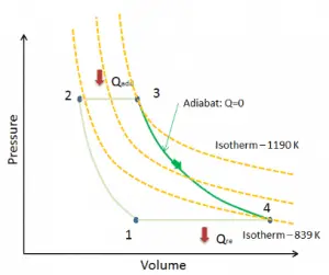
Assume an adiabatic expansion of helium (3 → 4) in a gas turbine. Since helium behaves almost as an ideal gas, use the ideal gas law to calculate the outlet temperature of the gas (T4,real). In these turbines, the high-pressure stage receives gas (point 3 at the figure; p3 = 6.7 MPa; T3 = 1190 K (917°C)) from a heat exchanger and exhausts it to another heat exchanger, where the outlet pressure is p4 = 2.78 MPa (point 4).
Solution:
The outlet temperature of the gas, T4,real, can be calculated using p, V, T Relation for the adiabatic process. Note that it is the same relation as for the isentropic process. Therefore results must be identical. In this case, we calculate the expansion for different gas turbines (less efficient) as in the case of Isentropic Expansion in Gas Turbine.
In this equation, the factor for helium is equal to κ=cp/cv=1.66. From the previous equation follows that the outlet temperature of the gas, T4,real, is:
See also: Mayer’s relation
Adiabatic Process in Gas Turbine
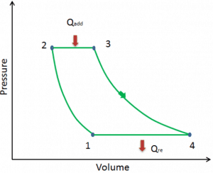
Let assume the Brayton cycle that describes the workings of a constant pressure heat engine. Modern gas turbine engines and airbreathing jet engines also follow the Brayton cycle.
The Brayton cycle consists of four thermodynamic processes. Two adiabatic processes and two isobaric processes.
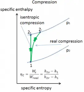
- Adiabatic compression – ambient air is drawn into the compressor, pressurized (1 → 2). The work required for the compressor is given by WC = H2 – H1.
- Isobaric heat addition – the compressed air then runs through a combustion chamber, burning fuel, and air or another medium is heated (2 → 3). It is a constant-pressure process since the chamber is open to flow in and out. The net heat added is given by Qadd = H3 – H2
- Adiabatic expansion – the heated, pressurized air then expands on a turbine, gives up its energy. The work done by the turbine is given by WT = H4 – H3
- Isobaric heat rejection – the residual heat must be rejected to close the cycle. The net heat rejected is given by Qre = H4 – H1
As can be seen, we can describe and calculate (e.g.,, thermal efficiency) such cycles (similarly for Rankine cycle) using enthalpies.
See also: Thermal Efficiency of Brayton Cycle
Isentropic Efficiency – Turbine, Compressor, Nozzle
In previous chapters, we assumed that the gas expansion is isentropic, and therefore we used T4,is as the gas´s outlet temperature. These assumptions are only applicable with ideal cycles.
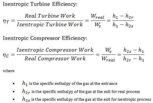
Most steady-flow devices (turbines, compressors, nozzles) operate under adiabatic conditions, but they are not truly isentropic but are rather idealized as isentropic for calculation purposes. We define parameters ηT, ηC, ηN, as a ratio of real work done by a device to work by a device when operated under isentropic conditions (in the case of the turbine). This ratio is known as the Isentropic Turbine/Compressor/Nozzle Efficiency.
These parameters describe how efficiently a turbine, compressor, or nozzle approximates a corresponding isentropic device. This parameter reduces the overall efficiency and work output. For turbines, the value of ηT is typically 0.7 to 0.9 (70–90%).
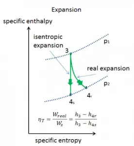
Example: Isentropic Turbine Efficiency

Assume an isentropic expansion of helium (3 → 4) in a gas turbine. In these turbines, the high-pressure stage receives gas (point 3 at the figure; p3 = 6.7 MPa; T3 = 1190 K (917°C)) from a heat exchanger and exhaust it to another heat exchanger, where the outlet pressure is p4 = 2.78 MPa (point 4). The temperature (for the isentropic process) of the gas at the exit of the turbine is T4s = 839 K (566°C).
Calculate the work done by this turbine and calculate the real temperature at the exit of the turbine when the isentropic turbine efficiency is ηT = 0.91 (91%).
Solution:
From the first law of thermodynamics, the work done by the turbine in an isentropic process can be calculated from:
WT = h3 – h4s → WTs = cp (T3 – T4s)
From Ideal Gas Law we know, that the molar specific heat of a monatomic ideal gas is:
Cv = 3/2R = 12.5 J/mol K and Cp = Cv + R = 5/2R = 20.8 J/mol K
We transfer the specific heat capacities into units of J/kg K via:
cp = Cp . 1/M (molar weight of helium) = 20.8 x 4.10-3 = 5200 J/kg K
The work done by gas turbine in isentropic process is then:
WT,s = cp (T3 – T4s) = 5200 x (1190 – 839) = 1.825 MJ/kg
The real work done by gas turbine in adiabatic process is then:
WT,real = cp (T3 – T4s) . ηT = 5200 x (1190 – 839) x 0.91 = 1.661 MJ/kg
Free Expansion – Joule Expansion
These are adiabatic processes in which no heat transfer occurs between the system and its environment, and no work is done on or by the system. These types of adiabatic processes are called free expansion. It is an irreversible process in which a gas expands into an insulated evacuated chamber. It is also called Joule expansion. For an ideal gas, the temperature doesn’t change (see: Joule’s Second Law). However, real gases experience a temperature change during free expansion. In free expansion, Q = W = 0, and the first law requires that:
dEint = 0
A free expansion can not be plotted on a P-V diagram because the process is rapid, not quasistatic. The intermediate states are not equilibrium states, and hence the pressure is not clearly defined.


