In general, it is not so simple to calculate pressure drops in fuel assemblies (especially the spacing grids), and it belongs to the key know-how of certain fuel manufacturers. Mostly, pressure drops are measured in experimental hydraulic loops rather than calculated.
Engineers use the pressure loss coefficient, PLC. It is noted K or ξ (pronounced “xi”). This coefficient characterizes pressure loss of a certain hydraulic system or a part of a hydraulic system, and it can be easily measured in hydraulic loops. The pressure loss coefficient can be defined or measured for both straight pipes and especially for local (minor) losses.
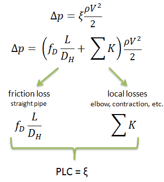
Using the below-mentioned example, the pressure loss coefficient (only frictional from the straight pipe) is equal to ξ = fDL/DH = 4.9. But the overall pressure loss coefficient (including spacing grids, top, and bottom nozzles, etc.) is usually about three times higher. This PLC (ξ = 4.9) causes the pressure drop to be of the order of (using the previous inputs) Δpfriction = 4.9 x 714 x 52/ 2 = 43.7 kPa (without spacing grids, top, and bottom nozzles). About three times higher real PLC means about three times higher Δpfuel will be.
The overall reactor pressure loss, Δpreactor, must include:
- downcomer and reactor bottom
- lower support plate
- fuel assembly including spacing grids, top and bottom nozzles, and other structural components – Δpfuel
- upper guide structure assembly
As a result, the overall reactor pressure loss – Δpreactor is usually of the order of hundreds kPa (let say 300 – 400 kPa) for design parameters.
It is an illustrative example, and previous data do not correspond to any reactor design.
See also: Fluid Acceleration – Pressure Loss
Example: Frictional Pressure Loss – Fuel Bundle
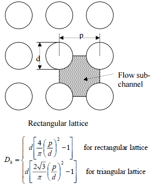 Calculate the frictional pressure loss of a single fuel rod inside a reactor core at normal operation (design flow rate). Assume that this fuel rod is part of a fuel bundle with the rectangular fuel lattice, and this fuel bundle does not contain spacing grids. Its height is h = 4m, and the core flow velocity is constant and equal to Vcore = 5 m/s.
Assume that:
- the outer diameter of the cladding is: d = 2 x rZr,1 = 9,3 mm
- the pitch of fuel pins is: p = 13 mm
- the relative roughness is ε/D = 5×10⁻⁴
- the fluid density is: ρ = 714 kg/m3
- the core flow velocity is constant and equal to Vcore = 5 m/s
- the average temperature of reactor coolant is: Tbulk = 296°C
Calculation of the Reynolds number
To calculate the Reynolds number, we have to know:
- the outer diameter of the cladding is: d = 2 x rZr,1 = 9,3 mm (to calculate the hydraulic diameter)
- the pitch of fuel pins is: p = 13 mm (to calculate the hydraulic diameter)
- the dynamic viscosity of saturated water at 300°C is: μ = 0.0000859 N.s/m2
- the fluid density is: ρ = 714 kg/m3
The hydraulic diameter, Dh, is a commonly used term when handling flow in non-circular tubes and channels. The hydraulic diameter of the fuel channel, Dh, is equal to 13,85 mm.
See also: Hydraulic Diameter
The Reynolds number inside the fuel channel is then equal to:
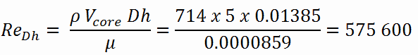
This fully satisfies the turbulent conditions.[/lgc_column]l