Power range detectors are key nuclear instrumentation systems for power operation. They monitor neutron flux (reactor power) from zero to about 120% of full rated power, indicating the power’s axial and radial distribution. They also provide indications, alarms, and reactor trip signals. As the neutron flux level increase into the power range, gamma compensation is not a major concern because gamma rays do not contribute much to the total ionization (about 0.1% at 100% power). Therefore, the power range instrumentation usually consists of four uncompensated ionization chambers, each with its own separate detector, cable run, and electronic circuitry. The ionization chamber, also known as the ion chamber, is an electrical device that detects various types of ionizing radiation. The voltage of the detector is adjusted so that the conditions correspond to the ionization region. The voltage is insufficient to produce gas amplification (secondary ionization). Ionization chambers are preferred for high radiation dose rates because they have no “dead time,” a phenomenon that affects the accuracy of the Geiger-Mueller tube at high dose rates. The detector consists of a single cylindrical chamber whose operation is identical to that of the boron-lined chamber of the compensated ion chamber. This uncompensated chamber is sensitive to both gamma rays and neutrons. However, in the power range of operation, the neutron flux level is many times greater than the gamma flux; therefore, no gamma compensation is required.
Since the neutrons are electrically neutral particles, they are mainly subject to strong nuclear forces, not electric ones. Therefore, neutrons are not directly ionizing and usually must be converted into charged particles before they can be detected. Generally, every type of neutron detector must be equipped with a converter (to convert neutron radiation to common detectable radiation) and one of the conventional radiation detectors (scintillation detector, gaseous detector, semiconductor detector, etc.).
Ionization chambers are often used as the charged particle detection device. For example, if the inner surface of the ionization chamber is coated with a thin coat of boron, the (n, alpha) reaction can occur. Most of (n,alpha) reactions of thermal neutrons are 10B(n,alpha)7Li reactions accompanied by 0.48 MeV gamma emission.
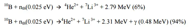
Moreover, isotope boron-10 has a high (n, alpha) reaction cross-section along the entire neutron energy spectrum. The alpha particle causes ionization within the chamber, and ejected electrons cause further secondary ionizations.
Another method for detecting neutrons using an ionization chamber is to use the gas boron trifluoride (BF3) instead of air in the chamber. The incoming neutrons produce alpha particles when they react with the boron atoms in the detector gas. Either method may be used to detect neutrons in a nuclear reactor. It must be noted that BF3 counters are usually operated in the proportional region.
All four channels are physically and functionally identical. Each power range channel employs an upper and a lower uncompensated ion chamber detector (tandem detector) which allows for the measurement of axial flux difference. Each channel also monitors a “quadrant” of the core. An upper and lower detector are mounted inside the same instrument well. The outputs of both detectors (upper and lower) are combined to produce a channel total power signal. The eight detector outputs (four uppers and four lower detectors) are compared to each other to provide power distribution information (AFD and QPTR) to the reactor operator.
The axial flux difference is defined as the difference in normalized flux signals (AFD) between the top and bottom halves of a two-section excore neutron detector, which will decrease.
AFD is defined as:
AFD or ΔI = Itop – Ibottom
where Itop and Ibottom are expressed as a fraction of rated thermal power.
QPTR is defined as:
The ratio of the maximum upper excore detector calibrated output to the average of the upper excore detector calibrated outputs, or the ratio of the maximum lower excore detector calibrated output to the average of the lower excore detector calibrated outputs, whichever is greater.
The power range instrumentation monitors and indicates the reactor core’s neutron flux level, the rate the neutron flux changes during a power operation, and the standard load that follows the operation. The neutron flux is indicated as a percentage of rated power. The rate of change of the neutron population is called startup rate (SUR), defined as the number of factors of ten that power changes in one minute. Therefore the units of SUR are powers of ten per minute or decades per minute (dpm).
Although the nuclear instrumentation system provides a prompt response to neutron flux changes and it is an irreplaceable system, it must be calibrated. Power range channels are calibrated to indicate percent rated thermal power by a secondary heat balance (calorimetric). The accurate thermal power of the reactor can be measured only by methods based on the energy balance of the primary circuit or the energy balance of the secondary circuit.
Special Reference: Standard Review Plan for the Review of Safety Analysis Reports for Nuclear Power Plants: LWR Edition. NUREG-0800, US NRC.
Neutron Flux and Fuel Burnup
In a power reactor, over a relatively short period (days or weeks), the atomic number density of the fuel atoms remains relatively constant. Therefore, in this short period, the average neutron flux remains constant when the reactor is operated at a constant power level. On the other hand, the atomic number densities of fissile isotopes for months decrease due to the fuel burnup, and therefore, also the macroscopic cross-sections decrease. This result slowly increases the neutron flux to keep the desired power level. Therefore, the excore nuclear instrumentation system must be periodically calibrated.
Power Range – Reactor Safety
As was written, the excore nuclear instrumentation system is considered a safety-related system because it provides inputs to the reactor protection system. The power range neutron flux trip provides the core protection for many power excursion accidents in MODE 1 (power operation). Examples of protective action signals provided by the power range include:
- The Power Range Neutron Flux (Low-Setpoint). A reactor trip will occur if the power level exceeds the preset value (for example, 25%) on two of four channels, and the trip is not blocked.
- The Power Range Neutron Flux (High-Setpoint). A reactor trip will occur if the power level exceeds the preset value (for example, 109%) on two of four channels to protect the core from an overpowering condition and to protect from a positive reactivity excursion leading to DNB during power operations. This trip cannot be blocked.
- Rate Trips. If the rate of change of reactor power exceeds a preset value in either the positive or negative direction, a reactor trip will occur.
- A high Positive Rate trip ensures that protection is provided against rapid increases in neutron flux characteristic of an RCCA drive rod housing rupture and the accompanying ejection of the RCCA.
- A high Negative Rate trip ensures protection for multiple rod drop accidents. At high power levels, a multiple rod drop accident could cause local flux peaking, resulting in a nonconservative local DNBR.