Self-Powered Neutron Detectors (SPND) are neutron detectors widely used in reactors to monitor neutron flux due to their adaptability for in-core severe environments. SPNDs may be a part of the incore neutron flux monitoring system, which provides detailed information on neutron flux distribution and thus the margins to these peak power limits. These detectors use its neutron activation material’s basic radioactive decay process to produce an output signal. As the name implies, SPNDs do not require an external voltage source to create a voltage potential in the detector. Instead, a current is produced in the detector as the result of neutron activation and subsequent beta decay of the detector itself. Because of the emission of these beta particles (electrons), the wire becomes more and more positively charged. The positive potential of the wire causes a current to flow in the resistor, R. The electron current from beta decay can be measured directly with an ammeter.
There are two main advantages of the self-powered neutron detector:
- Very little instrumentation is required, usually only a millivoltmeter or an ammeter
- The emitter material has a much greater lifetime than boron or uranium-235 lining used in fission chambers.
On the other hand, there are also disadvantages, and one is associated with the fact that currents, even at full power operation, are very low. Therefore, SPNDs cannot provide information about flux distribution at low power operation (10% and less). The main disadvantage of the self-powered neutron detector is that the emitter material decays with a characteristic half-life, which determines the detector’s response time. Depending on the response time, these detectors are broadly classified as:
- Prompt response detectors. The prompt response detectors such as Cobalt and Inconel are used in reactor protection and regulation applications.
- Delayed response detectors. The delayed response detectors like Vanadium and Rhodium are widely used for Flux Mapping System (FMS).
The typical SPND is a coaxial cable consisting of:
- Emitter. An inner electrode is made from a material that absorbs a neutron and undergoes radioactive decay by emitting an electron (beta decay). The emitter is usually made of rhodium and is used to produce electrons.
- Insulation. The emitter is surrounded by insulation, usually made of aluminum oxide.
- Collector. The metal walls of the detector encase these parts and serve as a collector for the produced electrons.- The collector is attached to ground potential,
Self-powered neutron detectors are usually placed into the instrumentation tube of a fuel assembly. They can monitor the entire length of selected fuel assemblies to provide an accurate, three-dimensional map of the neutron flux distribution. Neutron flux reconstruction can also be performed in the rest of the reactor core using these data.
Typical materials used for the emitter are cobalt, cadmium, rhodium, and vanadium. These materials should be used because they possess relatively high melting temperatures and high cross sections to thermal neutrons and are compatible with the SPND manufacturing process.
Special Reference: William H. Todt, Sr. CHARACTERISTICS OF SELF-POWERED NEUTRON DETECTORS USED IN POWER REACTORS. Imaging and Sensing Technology Corporation. New York.
Rhodium Emitter – Rhodium-based SPND
 One possible material is rhodium as the emitter. An SPND with a rhodium emitter has relatively high sensitivity, a high burn-up rate that perturbs the local power density, and a (two-fold) delayed signal. A Rhodium-based detector is the beta-current type of self-powered detector, which uses the following activation reaction to produce a current that can be measured.
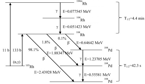
1n + 103Rh → 104Rh → 104Pd + β
As can be seen, a neutron captured by rhodium-103 causes a rhodium-103 atom to become a radioactive rhodium-104 atom. The rhodium-104 then decays into palladium-104 plus a beta particle (electron). The beta particle has enough energy to pass through the insulator and reach the collector. The half-life of activated rhodium-104 is 42.3 seconds, which delays the emission of the charged particle. The rhodium-based detector uses this production of beta particles (electrons) to create a current proportional to the number of neutrons captured by the emitter and local reactor power density. A portion of the detector’s current flow is due to gamma rays. A background correction is performed via a background detector consisting of the same components as the detector to compensate for this erroneous signal, except the rhodium is removed.
Rhodium-103 has a capture cross-section of 133 barns for thermal neutrons and a resonance at 1.25 eV. This reaction leads to the production of 104Rh with T1/2 = 42 sec, which is beta radioactive. It must be noted about 11 barns belong to a reaction in which an isomer 104mRh is produced (with T1/2 = 4.4 min).
The following characteristics are typical when used in thermal power reactors (e.g., PWR).
- The rhodium burn-up rate is 0.39% per month in a thermal neutron flux of 1013n/cm2/sec.
- 92% of the signal has a half-life of 42 seconds.
- 8% of the signal has a half-life of 4.4 minutes.
- The beta emission has an energy of 2.44 MeV.
Vanadium Emitter – Vanadium-based SPND
An SPND with a vanadium emitter has relatively low sensitivity, low burn-up rate, minimal perturbation of the local power density, and a very long delayed signal. A Vanadium-based detector is the beta-current type of self-powered detector, which uses the following activation reaction to produce a current that can be measured.
1n + 51V → 52V → 52Cr + β
Vanadium-51 has a capture cross-section of 4.9 barns for thermal neutrons without resonances. This reaction leads to the production of 52V with T1/2 = 3.74 min, which is beta radioactive.
The following characteristics are typical when used in thermal power reactors (e.g., PWR).
- The vanadium burnup rate is 0.012% per month in a thermal neutron flux of 1013n/cm2/sec.
- 99% of the signal has a half-life of 3.8 minutes.
- 1% of the signal is prompt.
- The subsequent beta emission has an energy of 2.6 MeV.