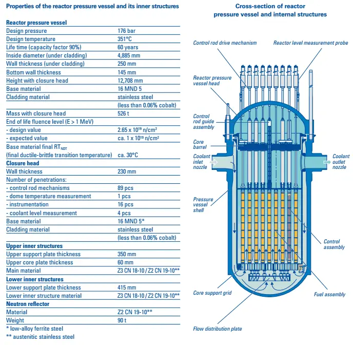
It is a cylindrical vessel with a hemispherical bottom head and a flanged and gasketed upper head. The bottom head is welded to the cylindrical shell while the top head is bolted to the cylindrical shell via the flanges. The top head is removable to allow for the refueling of the reactor during planned outages.

Source: gidropress.podolsk.ru
used with permission of АО ОКБ “ГИДРОПРЕСС”
One inlet (or cold leg) nozzle and one outlet (or hot leg) nozzle for each reactor coolant system loop. The reactor coolant enters the reactor vessel at the inlet nozzle. It exits the reactor at the upper internals region, where it is routed out the outlet nozzle into the hot leg of the primary circuit and goes on to the steam generator. The primary circuit of a typical PWR is divided into 4 independent loops (piping diameter ~ 800mm). Each loop comprises a steam generator and one main coolant pump but can differ according to certain reactor designs. Therefore, numerous inlet and outlet nozzles, control rod drive tubes (in case of BWRs), instrumentation, and safety injection nozzles penetrate the cylindrical shell. This number of inlet and outlet nozzles is a function of the number of loops.
The flow path for the reactor coolant through the reactor vessel would be:
- The coolant enters the reactor vessel at the inlet nozzle and hits against the core barrel.
- The core barrel forces the water to flow downward in the space between the reactor vessel wall and the core barrel, and this space is usually known as the downcomer.
- The flow is reversed up through the core from the bottom of the pressure vessel to pass through the fuel assemblies, where the coolant temperature increases as it passes through the fuel rods.
- Finally, the hotter reactor coolant enters the upper internals region, where it is routed out the outlet nozzle into the hot legs of the primary circuit and goes on to the steam generators.
The body of the reactor vessel is constructed of high-quality low-alloy carbon steel, and all surfaces that come into contact with reactor coolant are clad with a minimum of about 3 to 10 mm of austenitic stainless steel to minimize corrosion.
The reactor pressure vessels are the highest priority key components in nuclear power plants. The reactor pressure vessel houses the reactor core, and because of its function, it has direct safety significance. During the operation of a nuclear power plant, the material of the reactor pressure vessel is exposed to neutron radiation (especially to fast neutrons), which results in localized embrittlement of the steel and welds in the area of the reactor core. Radial neutron reflectors are installed around the reactor core to minimize such material degradation. There are two basic types of neutron reflectors, the core baffle, and the heavy reflector. Due to higher atomic number density, heavy reflectors reduce neutron leakage (especially of fast neutrons) from the core more efficiently than the core baffle. Since the reactor pressure vessel is considered irreplaceable, these aging effects of the RPV have the potential to be life-limiting conditions for a nuclear power plant.
Material Problems and Challenges of Nuclear Reactors
The main problems or rather challenges, that must be taken into account when designing reactors are:
- Pressure and temperature stress with associated limits
- Pressure and Temperature (P/T) Limits
- Heat up and cooldown rates
- Low-temperature Overpressure Protection Limits
- Pressurized Thermal Shock
- Radiation Damage to Reactor Materials
- Corrosion
See also: Material Problems of Nuclear Reactors
Special Reference: Reactor Pressure Vessel Status Report, U.S. NRC. NUREG-1511. Office of Nuclear Reactor Regulation U.S. Nuclear Regulatory Commission, Washington, 1994.
