
When located outside the containment building, the two areas are connected by a fuel transfer system which carries the fuel through a normally closed opening in the reactor containment. In this case, spent fuel is removed from the reactor vessel by a manipulator crane and placed in the fuel transfer system. In the spent fuel pool, the fuel is removed from the transfer system and placed into storage racks. After a suitable decay period, the fuel can be removed from storage and loaded into a shipping cask for removal from the site. Spent fuel pools are typically 12m or deeper, with the bottom equipped with storage racks designed to hold fuel assemblies removed from the reactor. A reactor’s pool is specially designed for the reactor where the fuel was used and situated at the reactor site.
Spent fuel pools are fitted with stainless steel and aluminum racks that hold the fuel assemblies and are lined with stainless steel to prevent leaking. No drains would allow the water level to drop or the pool to become empty. The plants have a variety of extra water sources and equipment to replenish the water that evaporates over time or in case of a leak. Plant personnel is also trained and prepared to respond to a problem quickly. The water serves two purposes: it cools the fuel and shields workers at the plant from radioactivity. Although water is neither high density nor high Z material, it is commonly used as a gamma shield. Water provides a radiation shielding of fuel assemblies in a spent fuel pool during storage or transport from and into the reactor core. Although water is a low-density material and low Z material, it is commonly used in nuclear power plants because these disadvantages can be compensated with increased thickness.
To conserve space, in all plants, open storage racks were replaced with so-called high-density racks that incorporate (boron-10) or other neutron-absorbing material to ensure subcriticality. Fuel assemblies can be stored in about one-half the volume required for storage in standard racks using such racks.
Spent nuclear fuel, also called the used nuclear fuel, is a nuclear fuel that has been irradiated in a nuclear reactor (usually at a nuclear power plant or an experimental reactor), and a fresh fuel must replace that due to its insufficient reactivity. Spent nuclear fuel is characterized by fuel burnup, a measure of how much energy is extracted from nuclear fuel, and a measure of fuel depletion. Due to fuel depletion and fission fragments buildup, spent nuclear fuel is no longer useful in sustaining a nuclear reaction in an ordinary thermal reactor and must be replaced by fresh fuel. It may have considerably different isotopic constituents depending on its point along the nuclear fuel cycle.
It must be noted that irradiated fuel is due to the presence of a high amount of radioactive fission fragments and transuranic elements that are very hot and very radioactive. Reactor operators have to manage the heat and radioactivity that remains in the “spent fuel” after it’s taken out of the reactor. In nuclear power plants, spent nuclear fuel is stored underwater in the spent fuel pool on the plant, and plant personnel moves the spent fuel underwater from the reactor to the pool. Over time, as the spent fuel is stored in the pool, it becomes cooler as the radioactivity decays away. After several years (> 5 years), decay heat decreases under specified limits so that spent fuel may be reprocessed or interim storage.
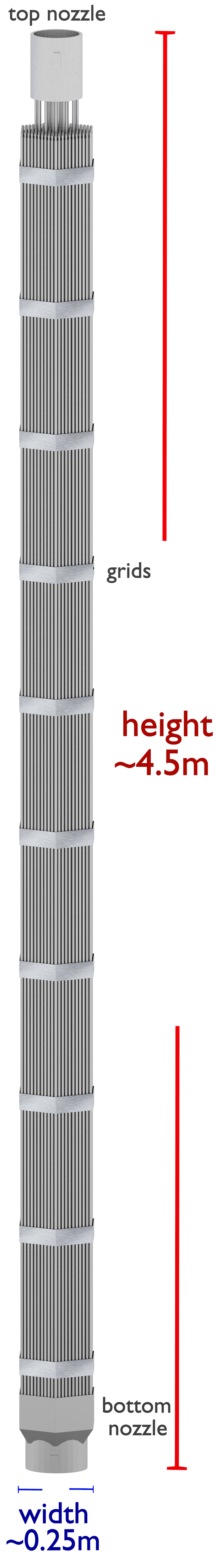
At first glance, it isn’t easy to recognize fresh fuel from used fuel. From a mechanical point of view, the used fuel (irradiated) is identical to the fresh fuel. In most PWRs, used fuel assemblies stand between four and five meters high, are about 20 cm across, and weigh about half a tonne. A PWR fuel assembly comprises a bottom nozzle into which rods are fixed through the lattice, and it is ended by a top nozzle to finish the whole assembly. There are spacing grids between these nozzles. These grids ensure an exact guiding of the fuel rods. The bottom and top nozzles are heavily constructed as they provide much mechanical support for the fuel assembly structure. Western PWRs use a square lattice arrangement, and assemblies are characterized by the number of rods they contain, typically 17×17 in current designs. In contrast to the fresh fuel, which is simply shiny, the oxide layer forming on the surface of used fuel assemblies during the four-year fuel cycle makes them dark. Moreover, Cherenkov radiation is typical only for spent nuclear fuel. The glow is also visible after the chain reaction stops (in the reactor). The Cherenkov radiation can characterize the remaining radioactivity of spent nuclear fuel, therefore it can be used for measuring fuel burnup.
Safety of Spent Fuel Pool
The safety of spent fuel pools stands on various criteria. These criteria may be grouped according to the following aspects:
- Subcriticality. Fulfillment of this criterion is based on:
- the design of the spent fuel pool,
- requirements on boric acid diluted in water,
- limiting of stored fuel (e.g., fuel enrichment, assembly burnup)
- Cooling. Fulfillment of this criterion is based on:
- the design of the spent fuel pool (e.g., no drains below the top of the stored fuel elements),
- requirements on the water level in the pool,
- requirements on active cooling elements (heat exchangers and heat sink).
- Radiation Shielding. Fulfillment of this criterion is based on:
- the design of the spent fuel pool (water and concrete shielding),
- the design of the surrounding working area
- requirements on the water level in the pool,
- Integrity. Fulfillment of this criterion is based on:
- the design of the spent fuel pool,
- the design of the surrounding working area,
- ensuring periodic inspections
Subcriticality of Spent Fuel Pool
As was written, subcriticality of the spent fuel pool is ensured by:
- the design of the spent fuel pool,
- requirements on boric acid diluted in water,
- limiting of stored fuel (e.g., fuel enrichment, assembly burnup)
Today, spent fuel is stored in so-called high-density racks or the maximum-density rack (MDR). Fuel assemblies can be stored in about one-half the volume required for storage in standard racks using such racks. Higher storage densities have been achieved without the risk of a nuclear chain reaction by adding neutron-absorbing materials (typically boron) to storage racks and baskets and dissolving them in the water. These racks incorporate (boron-10) or other neutron-absorbing material to ensure subcriticality. Boron-10 is generally present in the chemical form of boron carbide (B4C) within a metal matrix (e.g., Boral and Metamic (trademark of Metamic, LLC)) or a polymer matrix (e.g., Boraflex (trademark of BISCO), Carborundum, and Tetrabor). However, borated stainless steel incorporates the boron-10 atoms into the alloy composition.
In the high-density rack design, the spent fuel storage pool may be divided into two separate and distinct regions, which are considered separate pools for criticality considerations. In Region 2, maximum reactivity fuel is not allowed to load, while it can be loaded in the racks of Region 1 of the pool.
The most conservative approach requires that the multiplication factor, assuming flooding with pure water and infinite geometry, does not exceed 0.95 with full loading of the maximum anticipated enrichment. To satisfy this design criterion, the assumptions in the criticality evaluation are as below:
- The fuel assemblies have the maximum approved initial enrichment with the highest reactivity in the fuel’s lifetime and without the control rods (burnable poisons may be considered).
- In the flooding condition, all soluble poison is assumed to have been lost. Specify that the limiting keff of 0.95 (5% subcriticality) be evaluated in the absence of soluble boron.
- The array of the fuel assemblies can be taken as infinite geometry or with reflective boundary conditions.
- The effect of structural material and the fixed neutron absorber can be considered.
- Unless the double contingency principle is taken, the presence of the boron in the moderation should not be considered. This principle shows at least two independent, unlikely and concurrent incidents have to happen to lead to a criticality accident.
Boron Credit
The water in the spent fuel storage pool normally contains soluble boron, which results in large subcriticality margins under actual operating conditions. Boric acid is dissolved in the coolant, and Boric acid (molecular formula: H3BO3) is a white powder soluble in water. According to the NRC guidelines, based upon the accident condition in which all soluble poison is assumed to have been lost, specify that the limiting keff of 0.95 (5% subcriticality) be evaluated in the absence of soluble boron. Hence, the design of the spent fuel pool is based on the use of un-borated water. Unless the double contingency principle is taken, the presence of the boron (boron credit) in the moderation should not be considered. Nuclear plant owners face increasing fuel assembly enrichments, spent-fuel assembly burnup limitations, spent fuel pool storage cell restrictions, and problems with fixed neutron absorber degradation, all challenging their traditional criticality analyses. The credit for soluble boron (boron credit or partial boron credit – PBC) in the spent fuel pool criticality analysis offers a solution to these concerns.
For example, according to NUREG-0800 (9.1.1-4):
“For PWR pools where partial credit for soluble boron is taken, both of the following criteria must be met:
- When the spent fuel storage racks are loaded with the fuel of the maximum permissible reactivity and are flooded with full-density un-borated water, the maximum K(eff) must be less than 1.0 for all normal and credible abnormal conditions. The K(eff) must include allowance for all relevant uncertainties and tolerances.
- When the spent fuel storage racks are loaded with the fuel of the maximum permissible reactivity and are flooded with full-density water borated to a minimum concentration (CB,min, measured in parts per million of boron), the maximum K(eff) must be no greater than 0.95 for all normal conditions. Plant technical specifications must incorporate the CB,min. The K(eff) must include allowance for all relevant uncertainties and tolerances.”
Double Contingency Principle – Double Contingency Approach
“The double contingency approach requires a demonstration that unintended criticality cannot occur unless at least two unlikely, independent, concurrent changes in the conditions originally specified as essential to criticality safety have occurred.”
Source: Nuclear Safety Technical Assessment Guide. NS-TAST-GD-041 Revision 5. ONR, 2016.
The double contingency principle discussed in ANSI/ANS-8.1 allows credit for soluble boron under other abnormal or accident conditions since only a single accident needs to be considered at one time. For example, the most severe accident scenario is associated with fuel movement within the spent fuel pool and accidental misloading of a fuel assembly in the Region 2 of the spent fuel pool. This could potentially increase the criticality of Region 2. Boron is dissolved in the pool water to mitigate these postulated criticality-related accidents.
Burnup Credit
In criticality licensing of spent fuel pool, taking credit for the decrease in fuel reactivity due to fuel burnup is known as burnup credit. Burnup credit is similar to boron credit. The concept of burnup credit is taking credit for the reduction in reactivity due to irradiation of nuclear fuel when the criticality safety analysis is carried out for the spent fuel. In spent fuel storage, it has generally been required for criticality analyses to assume that fuel is at its peak reactivity, which is generally fresh fuel. But in the spent fuel pool, most fuel assemblies have higher burnup and lower reactivity.
The reduction of reactivity is a combinative effect of:
- the net reduction of fissile nuclides,
- the production of neutron-absorbing nuclides (non-fissile actinides and fission products)
In the high-density rack design, the spent fuel storage pool may be divided into two separate and distinct regions, which are considered separate pools for criticality considerations. There are two kinds of storage racks:
- The storage racks are applied to the spent fuel assemblies for which the burnup values must equal or more than the burnup value credited in the criticality safety calculation. (Region 2)
- The storage racks applied to the spent fuel assemblies assumed non-irradiated, with the maximum reactivity (Region 1).
It should be clear that the burnup credit is not an attempt to reduce the safety margins in criticality safety. It is to reduce the analysis conservatism and reduce the uncertainties in safety margins by a more accurate safety analysis. The fresh fuel assumption can be very conservative and significantly reduce the capacity for a storage or cask volume. The issue is complicated by ensuring adequate administrative controls and measurement systems exist to prevent higher reactivity fuel from being placed in storage racks. Regulators also have concerns about verifying the accuracy of being allowed burnup credit.
For example, abnormal conditions should include consideration of fuel assemblies loaded into storage racks not approved for storage (e.g., fuel not meeting minimum burnup requirements stored in burnup credit storage racks).
Special reference: Introduction of Burn-up Credit in Nuclear Criticality Safety Analysis. Guoshun You, Chunming Zhang, Xinyi Pan. Nuclear and Radiation Safety Center of MEP.
Cooling of Spent Fuel Pool
 It must be noted that irradiated fuel is due to the presence of a high amount of radioactive fission fragments and transuranic elements that are very hot and very radioactive. Reactor operators have to manage the heat and radioactivity that remains in the “spent fuel” after it’s taken out of the reactor. In nuclear power plants, spent nuclear fuel is stored underwater in the spent fuel pool on the plant, and plant personnel moves the spent fuel underwater from the reactor to the pool. Over time, as the spent fuel is stored in the pool, it becomes cooler as the radioactivity decays away. After several years (> 5 years), decay heat decreases under specified limits so that spent fuel may be reprocessed or interim storage.
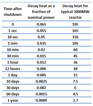
However, even at these low levels (about 0.25% after ten days), the heat generated requires continued heat removal for an appreciable time after shutdown. Decay heat is a long-term consideration and impacts spent fuel handling, reprocessing, waste management, and reactor safety.
The design of the reactor and the spent fuel pool must allow for the removal of this decay heat from the core by some means. If adequate heat removal is not available, decay heat will increase the temperatures in the fuel to the point that fuel melting and fuel assembly damage will occur, as in the case of Fukushima. The degree of concern with decay heat will vary according to reactor type and design.
As was written, cooling of the spent fuel pool is ensured by:
- the design of the spent fuel pool (e.g., no drains below the top of the stored fuel elements),
- requirements on the water level in the pool,
- requirements on active cooling elements (heat exchangers and heat sink).
The minimum water level in the fuel storage pool meets the assumptions of iodine decontamination factors following a fuel handling accident. The specified water level shields and minimizes the general area dose when the storage racks are filled to their maximum capacity. The water also provides shielding during the movement of spent fuel. But it also provides the coolant required for cooling spent fuel.
Cooling of the spent fuel pool is usually ensured by the spent fuel pool cooling system, designed to remove residual decay heat generated by spent fuel stored in the spent fuel pool. The system also maintains the purity of the spent fuel cooling water and the refueling water. The system is designed to cool stored spent fuel, and it may become necessary to cool all fuel assemblies from an unloaded reactor. The design incorporates redundant active components (usually 3×100%), and it is one of the safety systems. One of the principal safety functions of the ultimate heat sink (UHS) is a dissipation of maximum expected decay heat from the spent fuel pool to ensure the pool temperature remains within the design bounds for the structure.
Shielding of Spent Fuel in Spent Fuel Pool
It must be noted that irradiated fuel is due to the presence of a high amount of radioactive fission fragments and transuranic elements that are very hot and very radioactive. Reactor operators must manage the heat and radioactivity that remains in the “spent fuel” after it’s taken out of the reactor. In nuclear power plants, spent nuclear fuel is stored underwater in the spent fuel pool on the plant, and plant personnel moves the spent fuel underwater from the reactor to the pool. Over time, as the spent fuel is stored in the pool, it becomes cooler as the radioactivity decays away. After several years (> 5 years), decay heat and radioactivity decrease under specified limits so that spent fuel may be reprocessed or interim storage.
As was written, shielding of the spent fuel pool is ensured by:
- the design of the spent fuel pool (water and concrete shielding),
- the design of the surrounding working area
- requirements on the water level in the pool,
Spent fuel pools are fitted with stainless steel and aluminum racks that hold the fuel assemblies and are lined with stainless steel to prevent leaking. No drains would allow the water level to drop or the pool to become empty. The plants have a variety of extra water sources and equipment to replenish the water that evaporates over time or in case of a leak. Plant personnel is also trained and prepared to respond to a problem quickly. The water serves two purposes: it cools the fuel and shields workers at the plant from radioactivity. Although water is neither high density nor high Z material, it is commonly used as a gamma shield. Water provides a radiation shielding of fuel assemblies in a spent fuel pool during storage or transport from and into the reactor core. Although water is a low-density and low Z material, it is commonly used in nuclear power plants because these disadvantages can be compensated with increased thickness.
The minimum water level in the fuel storage pool meets the assumptions of iodine decontamination factors following a fuel handling accident. The specified water level shields and minimizes the general area dose when the storage racks are filled to their maximum capacity. The water also provides shielding during the movement of spent fuel. But it also provides the coolant required for cooling spent fuel.
Spent Fuel – Cherenkov Radiation
Cherenkov radiation is electromagnetic radiation emitted when a charged particle (such as an electron) moves through a dielectric medium faster than the phase velocity of light in that medium.
Cherenkov radiation can detect high-energy charged particles (especially beta particles). In nuclear reactors or a spent nuclear fuel pool, beta particles (high-energy electrons) are released as the fission fragments decay. The glow is also visible after the chain reaction stops (in the reactor). The Cherenkov radiation can characterize the remaining radioactivity of spent nuclear fuel and can be used for measuring fuel burnup.