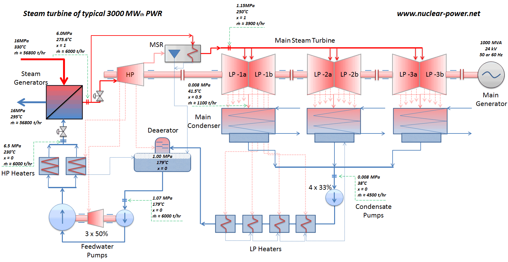
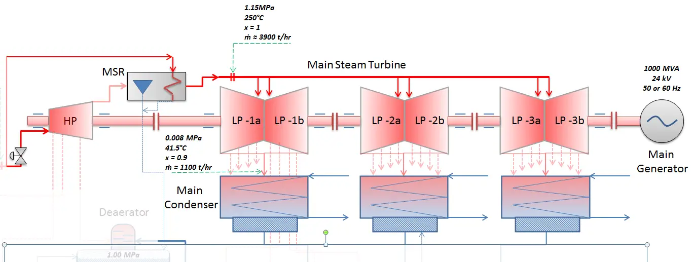
Most nuclear power plants operate a single-shaft turbine-generator that consists of one multi-stage HP turbine and three parallel multi-stage LP turbines, the main generator and an exciter. HP Turbine is usually a double-flow impulse turbine (or reaction type) with about 10 stages with shrouded blades and produces about 30-40% of the gross power output of the power plant unit. LP turbines are usually double-flow reaction turbines with about 5-8 stages (with shrouded blades and free-standing blades of the last 3 stages). LP turbines produce approximately 60-70% of the gross power output of the power plant unit. Each turbine rotor is mounted on two bearings, i.e., there are double bearings between each turbine module.
From Steam Generator to Main Steam Lines – Evaporation
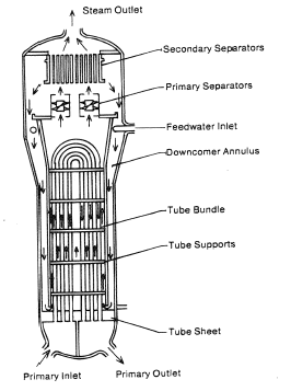
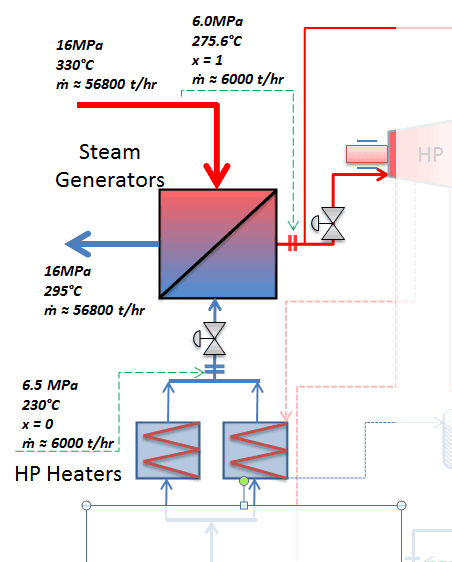
The power conversion system of typical PWR begins in the steam generators in their shell sides. Steam generators are heat exchangers that convert feedwater into steam from heat produced in a nuclear reactor core. The feedwater (secondary circuit) is heated from ~230°C 500°F (preheated fluid by regenerators) to the boiling point of that fluid (280°C; 536°F; 6,5MPa). Heat is transferred through the walls of these tubes to the lower pressure secondary coolant located on the secondary side of the exchanger where the coolant evaporates to pressurized steam (saturated steam 280°C; 536°F; 6,5 MPa). The saturated steam leaves the steam generator through a steam outlet and continues to the main steam lines and further to the steam turbine.
 These main steam lines are cross-tied (e.g.,, via steam collector pipe) near the turbine to ensure that the pressure difference between any steam generators does not exceed a specific value, thus maintaining system balance and ensuring uniform heat removal from the Reactor Coolant System (RCS). The steam flows through the main steam line isolation valves (MSIVs), which are very important to the high-pressure turbine from the safety point of view. Directly at the inlet of the steam turbine, there are throttle-stop valves and control valves. Turbine control is achieved by varying these turbine valves openings. In the event of a turbine trip, the steam supply must be isolated very quickly, usually in a fraction of a second, so the stop valves must operate quickly and reliably.
Calculate the amount of primary coolant, which is required to evaporate 1 kg of feedwater in a typical steam generator. Assume that there are no energy losses. This is only an idealized example.
Balance of the primary circuit
The hot primary coolant (water 330°C; 626°F; 16MPa) is pumped into the steam generator through the primary inlet. The primary coolant leaves (water 295°C; 563°F; 16MPa) the steam generator through the primary outlet.
hI, inlet = 1516 kJ/kg
=> ΔhI = -206 kJ/kg
hI, outlet = 1310 kJ/kg
Balance of the feedwater

The feedwater (water 230°C; 446°F; 6,5MPa) is pumped into the steam generator through the feedwater inlet. The feedwater (secondary circuit) is heated from ~230°C 446°F to the boiling point of that fluid (280°C; 536°F; 6,5MPa). Feedwater is then evaporated, and the pressurized steam (saturated steam 280°C; 536°F; 6,5 MPa) leaves the steam generator through the steam outlet and continues to the steam turbine.
hII, inlet = 991 kJ/kg
=> ΔhII = 1789 kJ/kg
hII, outlet = 2780 kJ/kg
Balance of the steam generator
Since the difference in specific enthalpies is less for primary coolant than for feedwater, it is obvious that the amount of primary coolant will be higher than 1kg. To produce 1 kg of saturated steam from feedwater, about 1789/206 x 1 kg = 8.68 kg of primary coolant is required.
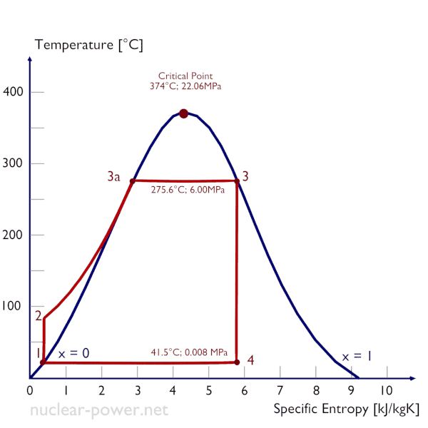
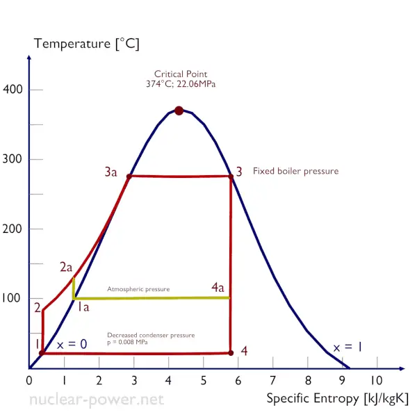
Isobaric heat addition (in a heat exchanger – boiler) – In this phase (between state 2 and state 3), there is a constant-pressure heat transfer to the liquid condensate from an external source since the chamber is open to flow in and out. The feedwater (secondary circuit) is heated to the boiling point (2 → 3a) of that fluid and then evaporated in the boiler (3a → 3). The net heat added is given by Qadd = H3 – H2
From Turbine Valves to Condenser – Expansion
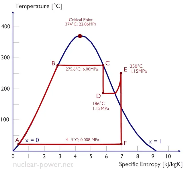
Typically most nuclear power plants operate multi-stage condensing steam turbines. In these turbines, the high-pressure stage receives steam (this steam is nearly saturated steam – x = 0.995 – point C at the figure; 6 MPa; 275.6°C) from a steam generator and exhausts it to moisture separator-reheater (MSR – point D). The steam must be reheated to avoid damages caused to the steam turbine blades by low-quality steam. High water droplets can cause rapid impingement and erosion of the blades, which occurs when condensed water is blasted onto the blades. To prevent this, condensate drains are installed in the steam piping leading to the turbine. The moisture-free steam is superheated by extraction steam from the high-pressure stage of the turbine and by steam directly from the main steam lines.
The heating steam is condensed in the tubes and is drained to the feedwater system. The reheater heats the steam (point D), and then the steam is directed to the low-pressure stage of the steam turbine, where it expands (point E to F). The exhausted steam then condenses in the condenser. It is at a pressure well below atmospheric (absolute pressure of 0.008 MPa) and is in a partially condensed state (point F), typically of a quality near 90%. The turbine’s high and low-pressure stages are usually on the same shaft to drive a common generator, but they have separate cases. The main generator produces electrical power, which is supplied to the electrical grid.
Isentropic expansion (expansion in a steam turbine) – Steam from the boiler expands adiabatically from state 3 to state 4 in a steam turbine to produce work and then is discharged to the condenser (partially condensed). The steam works on the surroundings (blades of the turbine) and loses an amount of enthalpy equal to the work that leaves the system. The work done by the turbine is given by WT = H4 – H3. Again the entropy remains unchanged.
From Condenser to Condensate Pumps – Condensation
 The main condenser condenses the exhaust steam from the main turbine’s low-pressure stages and the steam dump system. The exhausted steam is condensed by passing over tubes containing water from the cooling system.
The pressure inside the condenser is given by the ambient air temperature (i.e., water temperature in the cooling system) and by steam ejectors or vacuum pumps, which pull the gases (non-condensable) from the surface condenser eject them to the atmosphere.
The lowest feasible condenser pressure is the saturation pressure corresponding to the ambient temperature (e.g.,, the absolute pressure of 0.008 MPa, which corresponds to 41.5°C). Note that there is always a temperature difference between (around ΔT = 14°C) the condenser temperature and the ambient temperature, which originates from condensers’ finite size and efficiency. Since neither the condenser is a 100% efficient heat exchanger, there is always a temperature difference between the saturation temperature (secondary side) and the temperature of the coolant in the cooling system. Moreover, there is design inefficiency, which decreases the overall efficiency of the turbine. Ideally, the steam exhausted into the condenser would have no subcooling. But real condensers are designed to subcool the liquid by a few degrees Celsius to avoid the suction cavitation in the condensate pumps. But, this subcooling increases the inefficiency of the cycle because more energy is needed to reheat the water.
The goal of maintaining the lowest practical turbine exhaust pressure is a primary reason for including the condenser in a thermal power plant. The condenser provides a vacuum that maximizes the energy extracted from the steam, resulting in a significant increase in network and thermal efficiency. But also this parameter (condenser pressure) has its engineering limits:
- Decreasing the turbine exhaust pressure decreases the vapor quality (or dryness fraction). At some point, the expansion must be ended to avoid damages caused to steam turbine blades by low-quality steam.
- Decreasing the turbine exhaust pressure significantly increases the specific volume of exhausted steam, which requires huge blades in the last rows of the low-pressure stage of the steam turbine.
In a typical wet steam turbine, the exhausted steam condenses in the condenser, and it is at a pressure well below atmospheric (absolute pressure of 0.008 MPa, which corresponds to 41.5°C). This steam is in a partially condensed state (point F), typically of a quality near 90%. Note that the pressure inside the condenser is also dependent on the ambient atmospheric conditions:
- air temperature, pressure, and humidity in case of cooling into the atmosphere
- water temperature and the flow rate in case of cooling into a river or sea
An increase in the ambient temperature causes a proportional increase in pressure of exhausted steam (ΔT = 14°C is usually a constant); hence the thermal efficiency of the power conversion system decreases. In other words, the electrical output of a power plant may vary with ambient conditions, while the thermal power remains constant.
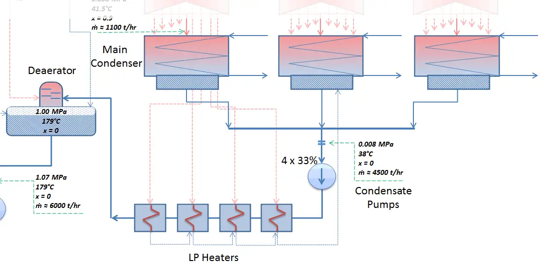
The condensed steam (now called condensate) is collected in the condenser’s hotwell. The condenser’s hotwell also provides a water storage capacity required for operational purposes such as feedwater makeup. The condensate (saturated or slightly subcooled liquid) is delivered to the condensate pump and then pumped by condensate pumps to the deaerator through a feedwater heating system. The condensate pumps increase the pressure usually to about p = 1-2 MPa. There are usually four one-third-capacity centrifugal condensate pumps with common suction and discharge headers. Three pumps are normally in operation, with one in the backup.
From Condensate Pumps to Feedwater Pumps – Heat Regeneration
The condensate from condensate pumps then passes through several stages of low-pressure feedwater heaters. The temperature of the condensate is increased by heat transfer from steam extracted from the low-pressure turbines. There are usually three or four stages of low-pressure feedwater heaters connected in the cascade. The condensate exits the low-pressure feedwater heaters at approximately p = 1 MPa, t = 150°C, entering the deaerator. The main condensate system also contains a mechanical condensate purification system for removing impurities. The feedwater heaters are self-regulating. It means that the greater the flow of feedwater, the greater the rate of heat absorption from the steam and the greater the flow of extraction steam.
There are non-return valves in the extraction steam lines between the feedwater heaters and the turbine. These non-return valves prevent the reverse steam or water flow in case of turbine trip, which causes a rapid decrease in the pressure inside the turbine. Any water entering the turbine in this way could cause severe damage to the turbine blading.
Deaerator
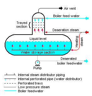
In general, a deaerator is a device used to remove oxygen and other dissolved gases from the feedwater to steam generators. The deaerator is part of the feedwater heating system. It is usually situated between the last low-pressure heater and feedwater booster pumps. In particular, dissolved oxygen in the steam generator can cause serious corrosion damage by attaching to the walls of metal piping and other metallic equipment and forming oxides (rust). Furthermore, dissolved carbon dioxide combines with water to form carbonic acid that causes further corrosion.
The condensate is heated to saturated conditions in the deaerator, usually by the steam extracted from the steam turbine. The extraction steam is mixed in the deaerator by a system of spray nozzles and cascading trays between which the steam percolates. Any dissolved gases in the condensate are released in this process and removed from the deaerator by venting to the atmosphere or the main condenser. Directly below the deaerator is the feedwater storage tank, in which a large quantity of feedwater is stored at near saturation conditions. This feedwater can be supplied to steam generators to maintain the required water inventory during the transient in the turbine trip event. The deaerator and storage tank are usually located at a high elevation in the turbine hall to ensure an adequate net positive suction head (NPSH) to the feedwater pumps at the inlet. NPSH is used to measure how close a fluid is too saturated conditions. Lowering the pressure at the suction side can induce cavitation. This arrangement minimizes the risk of cavitation in the pump.
From Feedwater Pumps to Steam Generator
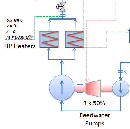 The system of feedwater pumps usually contains three parallel lines (3×50%) of feedwater pumps with common suction and discharge headers. Each feedwater pump consists of the booster and the main feedwater pump. The feed water pumps (usually driven by steam turbines) increase the pressure of the condensate (~1MPa) to the pressure in the steam generator (~6.5MPa).
The booster pumps provide the required main feedwater pump suction pressure. These pumps (both feedwater pumps) are normally high-pressure pumps (usually of the centrifugal pump type) that take suction from the deaerator water storage tank, which is mounted directly below the deaerator, and supply the main feedwater pumps. The water discharge from the feedwater pumps flows through the high-pressure feedwater heaters, enters the containment, and then flows into the steam generators.
Feedwater flow to each steam generator is controlled by feedwater regulating valves (FRVs) in each feedwater line. The regulator is controlled automatically by steam generator level, steam flow, and feedwater flow.
The high-pressure feedwater heaters are heated by extraction steam from the high-pressure turbine, HP Turbine. Drains from the high-pressure feedwater heaters are usually routed to the deaerator.
The feedwater (water 230°C; 446°F; 6,5MPa) is pumped into the steam generator through the feedwater inlet. In the steam generator is the feedwater (secondary circuit) heated from ~230°C 446°F to the boiling point of that fluid (280°C; 536°F; 6,5MPa). Feedwater is then evaporated, and the pressurized steam (saturated steam 280°C; 536°F; 6,5 MPa) leaves the steam generator through the steam outlet and continues to the steam turbine, thereby completing the cycle.