Axial Flux Difference – Axial Offset
 At power operation (i.e., above 1% of rated power), the reactivity feedbacks cause the flattening of the flux distribution because the feedbacks acts stronger on positions where the flux is higher. It follows there must be differences also in an axial direction.
For example, let assume the inlet temperature (Tin), determined by the pressure in the steam generators. Therefore the inlet temperature changes minimally as the thermal power changes. It follows the outlet temperature must change significantly as the thermal power increases. When the inlet temperature remains almost the same, and the outlet changes significantly, it stands to reason the average temperature of coolant (moderator) will also change significantly. It follows the temperature of the top half of the core increases (in case of power increase) more than the temperature of the bottom half of the core. Since the moderator temperature feedback must be negative, the power from the top half will shift to the bottom half. Hence the axial flux difference, defined as the difference in normalized flux signals (AFD) between the top and bottom halves of a two-section excore neutron detector, will decrease.
AFD is defined as:
AFD or ΔI = Itop – Ibottom
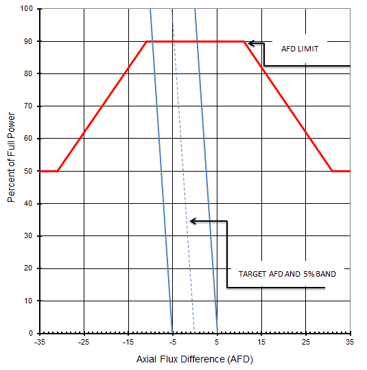
where Itop and Ibottom are expressed as a fraction of rated thermal power, as an example, assume the core is operating at 100% power. When the Itop = 49% and Ibottom = 51% the resulting ΔI = -2%. When the delta flux target is -5%. The core would then operate with a delta flux of -10% to 0%. The + 5% and -5% flux difference around the target allows for a small amount of movement of the control rods.
During power operation, the AFD is maintained within the specified limits. Compliance with the AFD limits prevents a highly top- or bottom skewed axial power distribution. By limiting the amount of power distribution skewing, core peaking factors are consistent with the assumptions used in the safety analyses. Limiting power distribution skewing over time also minimizes the xenon distribution skewing, a significant factor in axial power distribution control.
The operating scheme used to control the axial power distribution involves maintaining the AFD within a tolerance band around a burnup dependent target, known as the target flux difference, minimizing the variation of the axial peaking factor and axial xenon distribution during unit maneuvers.
For plants operating with so-called “constant axial offset control – CAOC”, the AFD limit involves a target band. This target band is, for example, +5% and -5% around the target value. Since the xenon concentration and distribution are flux and time-dependent, the longer the core operates outside its target band, the greater the probability of initiating a xenon transient.
At equilibrium xenon conditions, the target flux difference (ΔItarget) and its burnup dependent value are determined. The AFD is sensitive to many-core-related parameters such as control bank positions, core power level, axial burnup, axial xenon distribution, and, to a lesser extent, reactor coolant temperature and boron concentrations.
Constant Axial Offset Control (CAOC) is a strategy used to control axial power distribution in normal operations. CAOC requires that the AFD be controlled within a narrow tolerance band around a burnup-dependent target to minimize the probability of initiation xenon oscillations during power maneuvers. It also minimizes the variation of axial peaking factors.
Axial offset is defined as:
A/O = (Itop – Ibottom)/(Itop + Ibottom)
where Itop and Ibottom are expressed as a fraction of rated thermal power.
AFD and Safety Analyses
In summary, the AFD and the QPTR are direct and continuous measures of the core’s global power distribution. AFD measures global axial power distribution, whereas QPTR measures global azimuthal power distribution. Staying within their limits and proper operation of the control rods should continuously maintain acceptable peaking factors (FQ(z) and FΔH). The AFD and QPTR limits ensure that peaking factors (FQ(z) and FΔH) remain below their limiting values by preventing an undetected change in the gross axial and radial power distribution.
Together, the LCO limits on the AFD, the QPTR, the rod insertion limits and the power distribution (i.e., the Heat Flux Hot Channel Factor (FQ(z)), the Nuclear Enthalpy Rise Hot Channel Factor (FNΔH)) are established to preclude core power distributions that exceed the safety analyses limits.
Axial Offset Anomaly
As was written, the axial offset – A/O (or AFD) and the QPTR are direct and continuous measures of the core’s global power distribution. A/O measures global axial power distribution, whereas QPTR measures global azimuthal power distribution. Staying within their limits and proper operation of the control rods should continuously maintain acceptable peaking factors (FQ(z) and FΔH). The AFD and QPTR limits ensure that peaking factors (FQ(z) and FΔH) remain below their limiting values by preventing an undetected change in the gross axial and radial power distribution.
In the past, some PWR-type nuclear power plants (with LiOH water chemistry) have experienced small radial and especially axial offset anomalies (AOA). That means some PWRs have experienced an unexpected and gradual shift in the target flux difference (ΔItarget) towards more negative values – a shift of power from the top half to the bottom half.
After extensive research, it was found that AOA can be caused by crud buildup on high-power fuel assemblies, in which an increased subcooled nucleate boiling can occur. Since this subcooled nucleate boiling occurs in the upper part of the assembly, crud accumulation causes an accumulation of boron on the surface of the upper part of the assembly. Lithium borate is absorbed and concentrated in the crud layer, reducing the fission rate in the upper portion of the core. Not all reactor cores have experienced the AOA. It is now known that AOA is caused by a combination of high crud levels in the coolant, high boiling intensity in the core, and is strongly dependent on reactor water chemistry. Note that some reactor designs use LiOH to control the pH of the reactor coolant, and some use KOH.
As a result, during the fuel cycle, the neutron flux shifts from the top half to the bottom half and causes an increase in local peaking factors. Crud accumulation may also cause a reduction in available SDM (3-4 pcm/day). Near the end of the cycle, excess burnup in the bottom of the core and reduced boron and lithium concentrations in the reactor coolant system cause the power distribution to shift back toward the upper portion of the core, partially restoring the burnup distribution.
Special Reference: Information Notice No. 97-85: Effects of Crud Buildup and Boron Deposition on Power Distribution and Shutdown Margin, US NRC, 12/1997.