As was written, after synchronization of the generator, the reactor control system is usually switched to automatic control, and the additional power increase is in this mode. The power plant is then controlled by the plant control system that coordinates the NSSS and the turbine control system. The interfacing variable is, in this case, the core inlet temperature, which is fully determined by steam pressure inside steam generators. Note that the core inlet temperature and the steam pressure are interconnected since heat (or power) transferred across a steam generator is:
q = h . ΔT
where:
- q is the amount of heat transferred (heat flux), W/m2, i.e., thermal power per unit area
- h is heat transfer coefficient, W/(m2.K)
- ΔT is the difference in temperature across the steam generator (in this case, the difference between the average temperature of the reactor coolant – Tavg and the saturation temperature determined by system pressure.
For all practical purposes, the heat transfer coefficient (h) is constant since the heat transfer coefficient is a function of the materials used in constructing the steam generator. The U-tubes are completely covered with water.
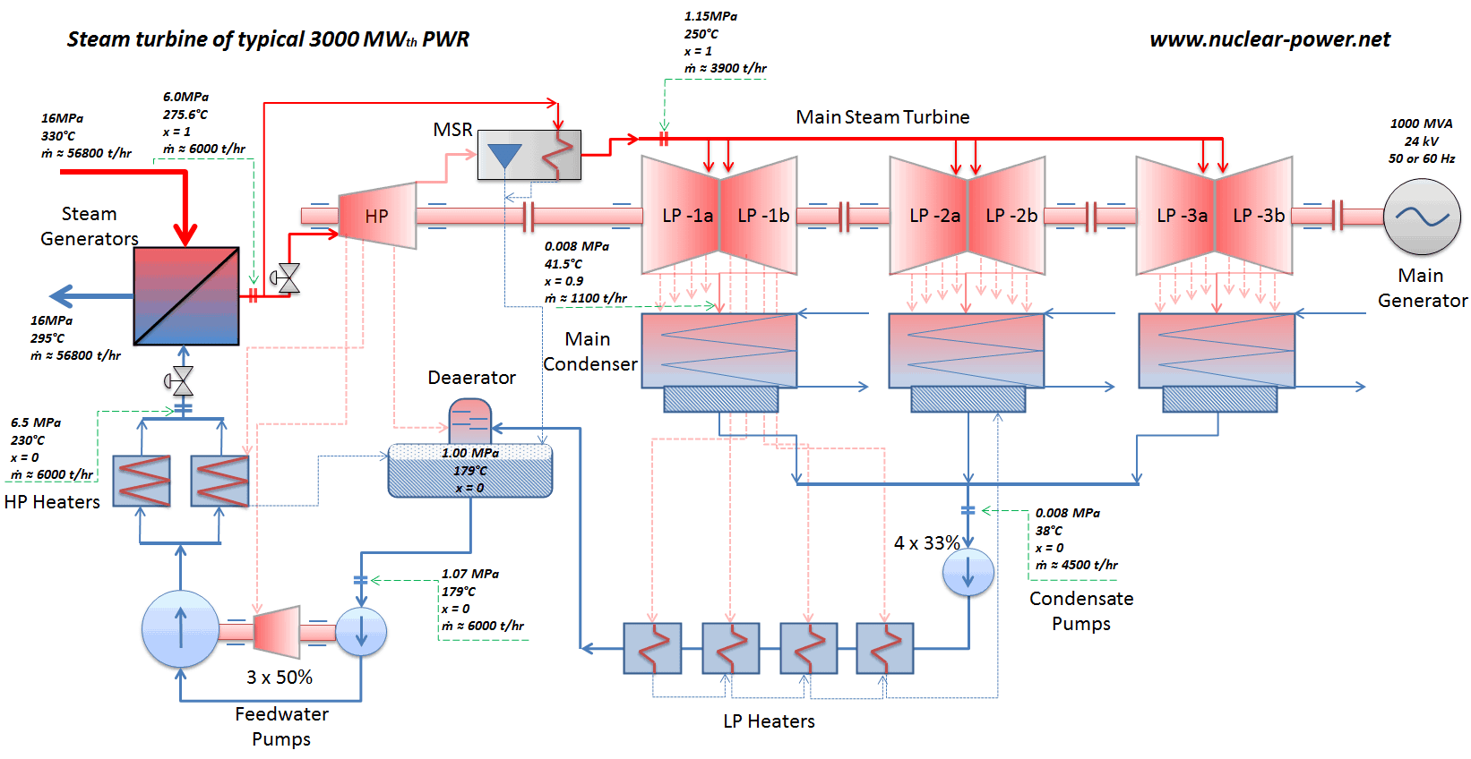
See also: Steam Turbine
A reactor is in automatic control follows the core inlet temperature – Tin (or the core average temperature – Tavg). Note that Tavg = (Tout + Tin) / 2. When there is a difference between the actual Tin and the temperature Tin set, which is set in the system, the reactor control system initiates control rods movement. For example, when Tin, actual > Tin, set, the reactor control system automatically inserts control rods to decrease Tin, actual. The reactor thermal power remains constant because the rod’s movement only offsets the reactivity from the difference (Tin, actual – Tin, set) x MTC = moderator defect.
On the other hand, if the energy demand in the external system increases, more energy is removed from the reactor system, causing the temperature of the reactor coolant (Tin) to decrease. As the reactor coolant temperature decreases, positive reactivity is added, resulting in a corresponding increase in reactor power level. This reactor power increase occurs without any change in control rods position and without any change in boron concentration. The same inherent stability can be observed as the energy demand on the system is decreased.
It must be added in case of disconnected automatic control, the turbine controls the steam pressure, and the reactor control system is in a manual regime. In this case, a control rods insertion causes a decrease in reactor thermal power since the steam pressure remains constant. The turbine load decreases as the reactor thermal power decreases.
See also: Reactor Stability
- Constant Pressure Regime (sliding Tavg). Constant pressure (psteam) regime means that the reactor control system maintains the steam pressure inside steam generators (or at the turbine inlet) constant as turbine load changes. Also, in this case, the automatic system follows Tavg, set, but Tavg, set is a function of turbine load. For example, increasing turbine load causes steam pressure to decrease. The reactor control system would sense this decrease in steam pressure and withdraw control rods to increase the reactor coolant temperature. This type of reactor control produces ideal steam conditions at the main turbine inlet for all loads from the initial load (e.g., 30%) to 100% load. The temperature difference (ΔT) between the primary and secondary sides is increased by raising Tavg or proportionally by raising Tin. The disadvantage of this type of control scheme is that minimal changes in turbine load require (negative MTC) intervention of the reactor control system. Moreover, there are problems within a high reactor outlet temperature (Tout), which approaches saturation values. Therefore it is not widely used in PWRs, especially U-tube steam generators.
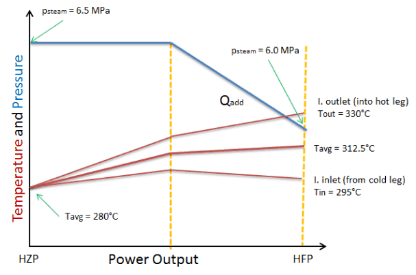
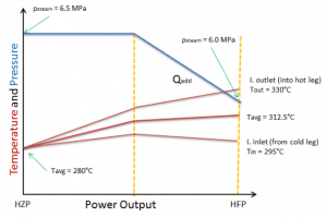
- Constant Tavg Regime (sliding psteam). Constant Tavg regime means that the reactor control system maintains the average core temperature of the reactor coolant constant as turbine load changes. The automatic system follows Tavg, set, which is constant. For example, increasing turbine load causes steam pressure to decrease. This, in turn, causes Tavg to decrease because the turbine uses more energy than that produced by the reactor. The reactor control system would sense this decrease in Tavg and withdraw control rods to increase the reactor coolant temperature. This regime causes minimal changes in the reactivity of the core due to minimal changes in the average coolant temperature. Since the coolant temperature remains constant, the coolant volume does not change, and therefore, the pressurizer level remains constant for all load conditions. The disadvantage of this type of control scheme is that steam conditions (steam pressure) significantly change from hot zero power to full load, which is unacceptable.
-
Sliding Tavg and Sliding psteam Regime. The automatic system follows Tavg, set, but Tavg, the set is a function of turbine load, and it is programmed for the best performance of the entire system. Sliding Tavg and Sliding psteam Regime. This regime combines the previous regimes. The automatic system follows Tavg, set, but Tavg, set is a function of turbine load, and it is programmed for the best performance of the entire system. Sometimes, there are many programmed functions of Tavg, set for different purposes (e.g., for initial power increase, load-follow, or coast down). The control scheme most often selected to control the reactor is the sliding Tavg and sliding psteam regime. This regime is a compromise between the other two regimes of control and contains some of the advantages and disadvantages of each.