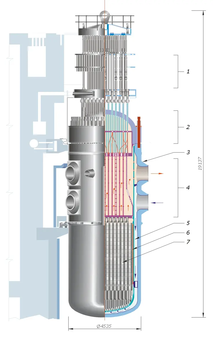
1) Control Element Drive Mechanism
2) Reactor vessel head
3) Reactor pressure vessel
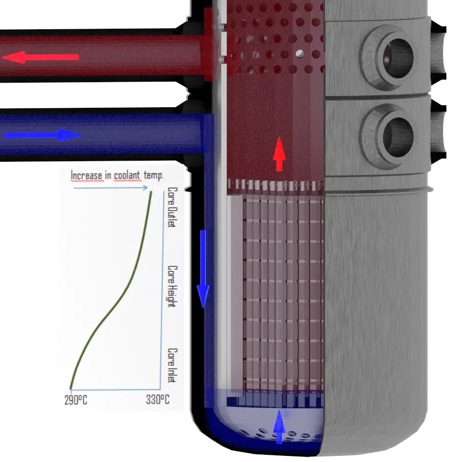
4) Coolant inlet-outlet nozzles
5) Downcomer for coolant
6) Neutron reflector
7) Fuel assemblies
Source: www.wikipedia.org
In general, the reactor thermal power and the outlet temperature of the coolant from the reactor core are controlled by manipulating several factors which affect the core’s reactivity. In PWRs, these factors are especially:
- position of control rods,
- the concentration of boric acid in the RCS
- core inlet temperature
Control Rods
Control rods are rods, plates, or tubes containing a neutron absorbing material (material with high absorption cross-section for thermal neutron) such as boron, hafnium, cadmium, etc., used to control the power of a nuclear reactor. Control rods usually constitute cluster control rod assemblies (PWR) inserted into guide thimbles within a nuclear fuel assembly. The absorbing material (e.g., pellets of Boron Carbide) is protected by the cladding, usually made of stainless steel. They are grouped into groups (banks), and the movement usually occurs by the groups (banks). The typical total number of clusters is 70. This number is limited, especially by the number of penetrations of the reactor pressure vessel head.
A control rod is removed from or inserted into the reactor core to increase or decrease the reactivity of the reactor (increase or decrease the neutron flux). Control rods (insertion/withdrawal) influence the thermal utilization factor. For example, control rods insertion causes the addition of new absorbing material into the core, and this causes a decrease in thermal utilization factor.
Compared with the chemical shim, which offset positive reactivity excess in the entire core, with control rods, the unevenness of neutron-flux density in the reactor core may arise because they act locally.
The concentration of Boric Acid
In pressurized water reactors, chemical shim (boric acid) is used to compensate for an excess of reactivity of reactor core along the fuel burnup (long term reactivity control) as well as to compensate for the negative reactivity from the power defect and xenon poisoning during power increase to nominal power.
The concentration of boric acid diluted in the primary coolant influences the thermal utilization factor. For example, an increase in the concentration of boric acid (chemical shim) causes the addition of new absorbing material into the core, and this causes a decrease in the thermal utilization factor.
Compared with burnable absorbers (long-term reactivity control) or with control rods (rapid reactivity control), the boric acid avoids the unevenness of neutron-flux density in the reactor core because it is dissolved homogeneously in the coolant in the entire reactor core. On the other hand, high concentrations of boric acid may lead to a positive moderator temperature coefficient, which is undesirable. In this case, more burnable absorbers must be used.
Moreover, this method is slow in controlling reactivity. Normally, it takes several minutes to change the boric acid concentration (dilute or borate) in the primary loop. For rapid changes of reactivity, control rods must be used.
Let’s assume that the reactor is critical at 75% of rated power and that the plant operator wants to increase power to 100% of rated power. The reactor operator must first bring the reactor supercritical by inserting a positive reactivity (e.g., by control rod withdrawal or boron dilution). As the thermal power increases, moderator temperature and fuel temperature increase, causing a negative reactivity effect (from the power coefficient), and the reactor returns to the critical condition. Positive reactivity must be continuously inserted (via control rods or chemical shim) to keep the power increasing. After each reactivity insertion, the reactor power stabilizes itself proportionately to the reactivity inserted. The total amount of feedback reactivity that must be offset by control rod withdrawal or boron dilution during the power increase (from ~1% – 100%) is known as the power defect.
Let assume:
- the power coefficient: Δρ/Δ% = -20pcm/% of rated power
- differential worth of control rods: Δρ/Δstep = 10pcm/step
- worth of boric acid: -11pcm/ppm
- desired trend of power decrease: 1% per minute
75% → ↑ 20 steps or ↓ 18 ppm of boric acid within 10 minutes → 85% → next ↑ 20 steps or ↓ 18 ppm within 10 minutes → 95% → final ↑ 10 steps or ↓ 9 ppm within 5 minutes → 100%
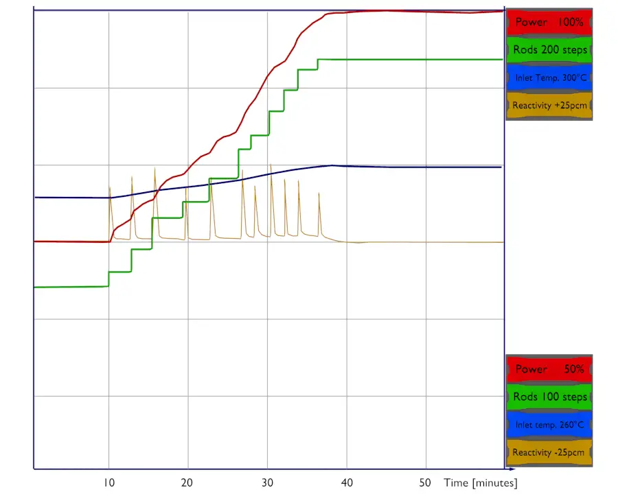
The power distribution significantly changes also with changes in the thermal power of the reactor. During power changes at power operation mode (i.e., from about 1% up to 100% of rated power), the temperature reactivity effects play a very important role. As the neutron population increases, the fuel and the moderator increase their temperature, which results in a decrease in reactivity of the reactor (almost all reactors are designed to have the temperature coefficients negative). The negative reactivity coefficient acts against the initial positive reactivity insertion, and this positive reactivity is offset by negative reactivity from temperature feedbacks.
This effect naturally occurs on a global scale and a local scale.
During thermal power increase, the effectiveness of temperature feedbacks will be greatest where the power is greatest. This process causes the flattening of the flux distribution because the feedback acts stronger on positions where the flux is higher.
It must be noted the effect of change in the thermal power have significant consequences on the axial power distribution (global power distribution).
In reality, when there is a change in the thermal power, and the coolant flow rate remains the same, the difference between inlet and outlet temperatures must increase. It follows from the basic energy equation of reactor coolant, which is below:
P=↓ṁ.c.↑∆t
Power increase. Let’s assume that the reactor is critical at 75% of rated power and that the plant operator wants to increase power to 100% of rated power.
The inlet temperature is determined by the pressure in the steam generators; therefore, the inlet temperature changes minimally during the change of thermal power. It follows the outlet temperature must change significantly as the thermal power changes. When the inlet temperature remains almost the same, and the outlet changes significantly, it stands to reason the average temperature of coolant (moderator) will also change significantly. It follows the temperature of the top half of the core increases more than the temperature of the bottom half of the core. Since the moderator temperature feedback must be negative, the power from the top half will shift to the bottom half. In short, the top half of the core is cooled (moderated) by hotter coolant, and therefore it is worse moderated. Hence the axial flux difference, defined as the difference in normalized flux signals (AFD) between the top and bottom halves of a two-section excore neutron detector, will decrease.
AFD is defined as:
AFD or ΔI = Itop – Ibottom
where Itop and Ibottom are expressed as a fraction of rated thermal power.