A reactor startup is a procedure that comprises many points and changes of operational parameters and significantly differs according to certain reactor types. For example, any startup of zero-power reactors (e.g., research reactors) can be classified into three categories:
- Normal Startup. The normal startup is the routine restart of a reactor. Restarts are possible if all reactivity characteristics (fuel, control rods, experimental channels) remain, and all these reactivity characteristics and the control rod positions in the critical condition of the reactor are known.
- Comprehensive Startup Experiment. It is necessary for a safe reactor startup after minor material or geometry changes that do not require a critical experiment.
- Critical Experiment. A critical experiment has to be carried out if all reactivity characteristics (e.g., critical mass, reactivity characteristics of the control rods, excess reactivity, etc.) were changed and all these reactivity characteristics and the control rod positions in the critical condition of the reactor are experimentally unconfirmed (are known only computationally). This applies, in any case, to the first startup of a new build reactor and any further startup after variations of the assembly, which let expect a considerable change in the reactivity behavior.
For power reactors, such as for PWRs, reactor startups are usually classified also into three categories:
- Reactor Startup after Normal Shutdown. Sometimes, a reactor must be shutdowned without refueling. In this case, a reactor startup is a routine issue since all reactivity characteristics and estimated critical conditions are well known. Such a shutdown usually (e.g., a restart following a turbine trip) does not require the Reactor Coolant System (RCS) to be cooled down and depressurized. Therefore may take only several hours because a startup from a hot condition does not need plant heat up and physics tests.
- Reactor Startup after Refueling. During refueling, every 12 to 18 months, some of the fuel – usually one-third or one-quarter of the core – is removed to the spent fuel pool. At the same time, the remainder is rearranged to a location in the core better suited to its remaining level of enrichment. Changes in loading pattern significantly change especially neutronic parameters of a core. In conjunction with each refueling or other significant reactor core alternation, physics tests are required to determine if the operating characteristics of the core are consistent with the core design calculations (pre-calculated). It may take several days.
- Initial Reactor Startup. Initial reactor startup has to be carried out for the successful commissioning of a nuclear power plant, and it comprises many other tests, such as hydraulic and pressure tests. It may take several months.
As presented here by the following points, the startup applies to a reactor startup after refueling. This procedure briefly describes a typical plant startup from a cold shutdown state. It is assumed that all pressure tests were successful.
From Cold Zero Power (CZP) to Hot Full Power (HFP)
- Plant Heatup.
- Startup to Minimum Load.
- Reload Startup Physics Tests.
- Synchronization of the Generator
- Normal Operation – Full Power
Plant Heatup
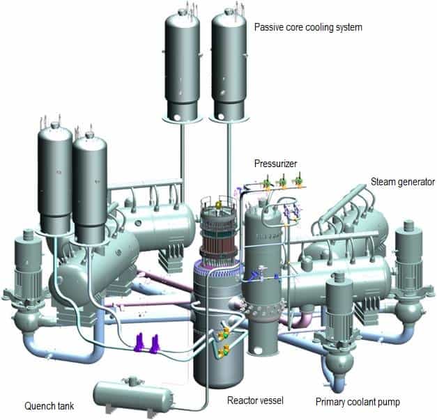
Source: gidropress.podolsk.ru
used with permission of АО ОКБ “ГИДРОПРЕСС”
In general, a reactor startup after refueling is a startup from a cold condition since refueling requires the Reactor Coolant System (RCS) to be cooled down and depressurized. The initial conditions are the NSSS – Nuclear Steam Supply System is in the “cold shutdown” mode, which means Tavg = 30°C, pressure = near atmospheric, boron concentration is sufficient to yield 10% shutdown margin, and RCPs – Reactor Coolant Pumps are off. Prior to each point of the procedure above, compliance with the plant Technical Specifications must be verified.
The NSSS heat up from Cold Shutdown (MODE 5) to Hot Standby (MODE 3) is performed by reactor coolant pumps which are very powerful (they can consume up to 6 MW each), and therefore its work together with a decay heat can be used for heating the primary coolant before a reactor startup. Reactor coolant system pressure must be increased to satisfy net positive suction head requirements to operate the reactor coolant pumps. Reactor coolant pumps are started sequentially. The primary plant heat-up rate is limited to about 30°C per hour to minimize internal stress in the material of the pressure vessel, primary piping, and other components.
The RCPs are used because a pressurized water reactor may have a positive moderator temperature coefficient at low temperatures. An operation (reactor criticality) with a positive moderator temperature coefficient caused by the amount of soluble boron in the moderator (see: MTC) is prohibited. Therefore the heat up by chain fission reaction is prohibited. The plant is brought to near operating temperatures (e.g., Tin ~ 275°C) with reactor coolant pump heat before the reactor is made critical. Heat exchangers of the residual heat removal system are bypassed to allow heat up. Since the coolant volume increases (due to thermal expansion) during its heat up, its excess must be removed from the reactor coolant system.
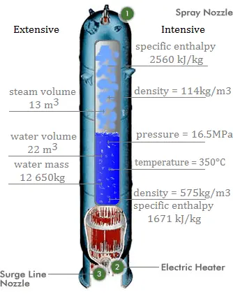
Pressure in the pressurizer is controlled by varying the temperature of the coolant in the pressurizer. For these purposes, two systems are installed. Water spray system and electrical heaters system. The submerged electrical heaters are designed to increase the pressure by evaporating the water in the vessel and to heat up the pressurizer. Water pressure in a closed system tracks water temperature directly; as the temperature rises, the pressure goes up.
When the reactor coolant temperature and pressure reach the target value (e.g., 275°C and 16 MPa), the RCS heat up is finished. The temperature of the coolant is then maintained through the balanced use of reactor coolant pump heat input and a steam dump system that releases steam to the main condenser. The next step in the plant’s startup is to take the reactor critical.
Criticality Approach – Startup to Minimum Load
The process of reaching criticality (i.e., keff = 1) is known as the criticality approach or startup to minimum load. Prior to this process, the boron concentration is usually sufficient (after refueling) to yield ~10% shutdown margin (i.e., keff = 0,90), the control rods are fully inserted into the core. If allowed, the boron concentration can be adjusted to the required value prior to startup.
For the criticality approach, parameters known as estimated critical conditions must be known. Estimated critical conditions are pre-calculated for each fuel loading pattern and usually consist from:
- Estimated critical rod position (e.g., the last control rod bank at 90% of the core height)
- Estimated critical boron concentration (e.g., cB = 9 g/kg = 1573 ppm)
- Estimated critical core inlet temperature (e.g., Tin = 275°C)
These three parameters together specifies the estimated critical state. The control rods must satisfy the requirement known as the rod insertion limit, and the rod insertion limit ensures shutdown margin requirements. There are many ways how to reach a critical state, but usually, the following two procedures are used:
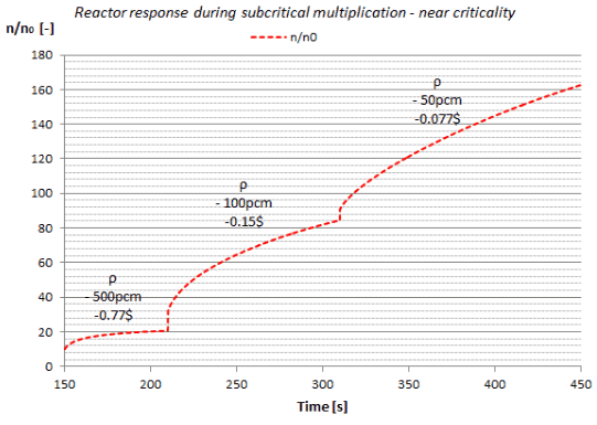
- Approach by control rods withdrawal. When the existing boron concentration is near the estimated critical, the approach can be performed only by control rods withdrawal. Sometimes the boron concentration can be adjusted to the required value prior to startup, and then this procedure can be used. The control rods are withdrawn from the core in successive steps. The shutdown rod banks are withdrawn in sequence, and then the control banks are withdrawn manually to achieve criticality. Following each step, the neutron count rate is registered. Experimentally the neutron count rate is measured by source range neutron detectors (usually three in the 120° symmetry) located at different positions outside the reactor. The neutron level following each addition of reactivity should be allowed to stabilize to obtain an accurate indication of asymptotic multiplication before proceeding with the next reactivity addition. This stabilization time becomes progressively larger as criticality is approached.
- Approach by boron dilution. When the existing boron concentration is far from the estimated critical, and the adjustment is not allowed, the critical state must be approached by boron dilution. Prior to boron dilution, the shutdown and control rods are withdrawn to estimated critical condition (e.g., all at ARO position except the last control rod bank, which is withdrawn to 90% of the core height). Then the boron concentration can be lowered by introducing condensate into the reactor coolant system. This process is not performed by steps. Therefore, there is no stabilization to obtain an accurate indication of asymptotic multiplication. Also, in this case, the neutron count rate is measured by source range neutron detectors.
See also: Subcritical Multiplication
Evidence of criticality is indicated by a positive, sustained startup rate or by reactimeter with no rod motion and increasing source range counts. After criticality is achieved, a positive startup rate is established (reactor is slightly supercritical), and the power level increases up to “minimum load”. This power increase is then stabilized at minimum load by control rods insertion. At minimum load, the power level does not influence the criticality (keff) of a power reactor unless thermal reactivity feedbacks act (operation of a power reactor without reactivity feedbacks is between 10E-8% – 1% of rated power). The reactor behaves as a “zero power reactor”.
It is very important to pay attention to safety instructions. Since the reactor is at low power, the reactor is far from temperature feedback, improving reactor stability. There is a possibility that automatic shutdown, which can be activated by a reactor protection system in case too much reactivity is inserted.
The inherent power stability is ineffective below the point known as the “point of adding heat”. Suppose a power excursion is initiated from a very low power level. In that case, power will continue to rise unchecked until the point of adding heat is reached, and the subsequent temperature rise adds negative reactivity to slow the rise of reactor power.
See also: 1/M Plot
See also: Source Neutrons
Reload Startup Physics Tests
In conjunction with each refueling or other significant reactor core alternation, reactor startup physics tests are required to determine if the operating characteristics of the core are consistent with the core design calculations (pre-calculated). Therefore key nuclear safety parameters must also be verified experimentally during physics tests at low power.
Key nuclear safety parameters are selected as a minimal set of parameters that describes the behavior of a reactor core during transients and accidents assumed in safety analyses (SAR).
The set of key nuclear safety parameters selected for low power physics tests includes:
- Reactivity balance
- Measurement of critical boron concentration
- Flux symmetry measurements
- Reactivity coefficients such as:
- Moderator temperature coefficient
- Moderator density reactivity coefficient
- Boron reactivity coefficient
- Reactivity control:
- Control rod worths
- Immediate reactivity after reactor trip
Following the low power physics tests, the power distribution must be verified. Power distribution tests are performed at higher power levels (e.g., between 30% – 50% of rated power).
See also: Initial Test Programs for Water-cooled Nuclear Power Plants, Regulatory Guide 1.68, U. S. Nuclear Regulatory Commission, June 2013.
See also: Reload startup physics tests for pressurized water reactor, American National Standard, ANSI/ANS – 19.6.1-2011, January 2011.
Synchronization of the Generator
Following the low power physics tests, the reactor power is increased by further control rods withdrawal to about 10 – 30% of rated thermal power. The reactor is now at zero electrical loads, and all the thermal energy generated is bypassed by the turbine bypass system (TBS) directly to the main condensers.
At this point, the turbine is accelerated to synchronous speed and connected with the grid. Synchronization is the process of matching the speed and frequency of a generator or other source to a running network. The turbine-generator must have equal line voltage, frequency, phase sequence, phase angle, and waveform to the system to which it is being synchronized. As turbine-generator loading is started (turbine control valves open), the turbine bypass valves will ramp shut at a rate that maintains steam pressure until they are fully closed.
At this point, an additional power increase is usually switched to automatic control. After determining that all systems (NSSS and Turbine-generator) are functioning properly at the initial load, the plant loading is continued to full power at a limited rate. This rate usually does not exceed 5 percent of rated power per minute. After refueling, the power increase can be further limited to minimize fuel cladding strain.
Conditions for Synchronization of Generator

As was written, synchronization is the process of matching the speed and frequency of a generator or other source to a running grid. The turbine-generator must have equal line voltage, frequency, phase sequence, phase angle, and waveform to the system to which it is being synchronized. An improper synchronization can result in electrical and mechanical transients that damage the generator, transformers, and other power system components.
Typically the main generator operates at speeds about:
- 3000 RPM for 50 Hz systems for 2-pole generator (or 1500 RPM for 4-pole generator),
- 1800 RPM for 60 Hz systems for 4-pole generator (or 3600 RPM for 2-pole generator).
With an output voltage of 24,000 volts (i.e., 24 kV), nominal rating – 1111 MVA, effective power – 1000 MWel, power factor – 0,9, and efficiency – 99%.
Thus, synchronizing requires the following conditions of the incoming generator:
- Correct phase sequence and waveform. This requirement must be verified during the initial installation of the generator or after maintenance. Connecting a generator with the wrong phase sequence will result in a short circuit as the system voltages are opposite to those of the generator terminal voltages.
- The frequency is almost exactly equal to that of the system. The generator is brought up to approximate synchronous speed by supplying more mechanical energy to its shaft – for example, opening the control valves on a steam turbine. Improper matching of frequency results in high acceleration and deceleration of a turbine.
- Zero phase angle. The phase angle between the incoming generator voltage and the voltage of the bus bar should be zero.
- Machine terminal voltage is approximately equal to the system voltage.
- Phase voltages in phase with those of the system. Machine terminal voltage and phase voltages can be adjusted by exciter and must be controlled each time a generator is connected to a grid.
As can be seen, synchronization matches various parameters of one generator to another generator or the bus bar. As a result, all generators connected in the grid rotate identically with identical speed and in the same phase sequence. The process of synchronization is also called as paralleling of alternators.
Synchronizing Lamps – Synchroscope Method
Different methods are being available for the synchronization of generators. All these methods are based on the check of all five conditions discussed above. The common methods used for synchronizing the generators are given below.
Synchronizing Lamps
The Synchronizing lamps method usually uses three lamps connected between the generator and system terminals. Each of which is rated for generator terminal voltage. The lights will flicker at the frequency proportional to the difference between generator and system frequencies as the generator speed changes. When the voltage at the generator is opposite to the system voltage, the lamps will be bright. On the other hand, when the voltage at the generator matches the system voltage, the lights will be dark. At the moment when all the conditions of parallel operation are satisfied, the lamps should be more or less dark. If lamps flicker concurrently, indicating that the phase sequence of the generator matches with the grid. On the other hand, if they flicker one after another, it resembles the incorrect phase sequence.
Synchroscope Method
A synchroscope is a device that indicates the degree to which two systems (e.g., generators) are synchronized with each other. A synchroscope is used for indicating the appropriate moment for synchronization. Synchroscopes measure and display the frequency difference and phase angle between two power systems. The synchroscope has a circular dial over which a pointer is hinged capable of rotating in clockwise and anticlockwise directions. The pointer of the synchroscope will indicate the “fast” or “slow” speed of the generator for the system. If the generator is turning at a lower frequency than the grid, the synchroscope pointer rotates continually in the direction (usually counterclockwise). If the generator is turning at a higher frequency than the grid, the synchroscope pointer rotates continually in the opposite direction (usually clockwise). When these two quantities (difference in frequencies and phase angles) are zero (the pointer stops rotating), it is safe to connect the two systems together. After the machine has been synchronized and is part of the system, it can take its share of the active power by appropriate adjustments of its control valves.