An understanding of materials science is essential for power plant personnel to understand why material was selected for certain applications within their facility. Almost all processes that take place in nuclear facilities involve the use of specialized metals. A basic understanding of material science is necessary for nuclear facility operators, maintenance personnel, and the technical staff to operate and maintain the facility and facility support systems safely. Our goal here will be to briefly describe the basic materials considerations of nuclear reactors. The knowledge of thermophysical and nuclear properties of materials is essential for designing nuclear power plants.
Materials for Nuclear Reactors
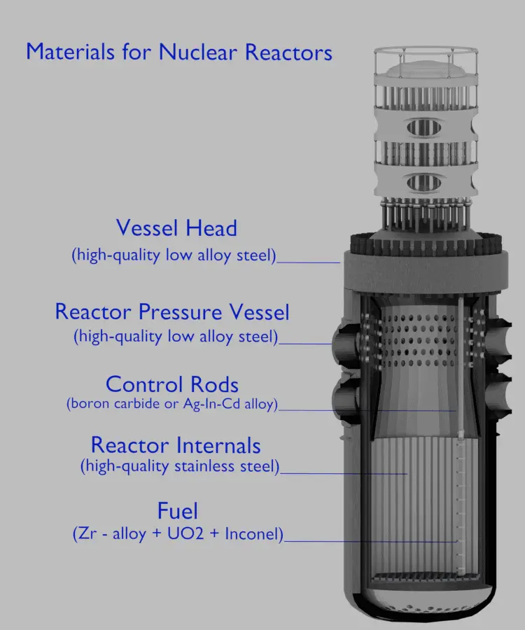
Pressurized water reactors use a reactor pressure vessel (RPV) to contain the nuclear fuel, moderator, control rods, and coolant. They are cooled and moderated by high-pressure liquid water (e.g., 16MPa). At this pressure, water boils at approximately 350°C (662°F). The inlet temperature of the water is about 290°C (554°F). The water (coolant) is heated in the reactor core to approximately 325°C (617°F) as the water flows through the core. As it can be seen, the reactor has approximately 25°C subcooled coolants (distance from the saturation).
The reactor pressure vessel is the pressure vessel containing the reactor core and other key reactor internals. It is a cylindrical vessel with a hemispherical bottom head and a flanged and gasketed upper head. The bottom head is welded to the cylindrical shell, while the top head is bolted to the cylindrical shell via the flanges. The top head is removable to allow for the refueling of the reactor during planned outages.
The body of the reactor vessel is constructed of high-quality low-alloy carbon steel, and all surfaces that come into contact with reactor coolant are clad with a minimum of about 3 to 10 mm of austenitic stainless steel (e.g., 304L) in order to minimize corrosion.
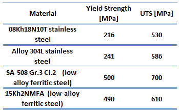 Low-carbon steel, also known as mild steel, is now the most common form of steel because its price is relatively low while it provides material properties that are acceptable for many applications. Low-carbon steel contains approximately 0.05–0.25% carbon making it malleable and ductile. Mild steel has a relatively low tensile strength, but it has high toughness, and it is easy to form. Special requirements for materials of reactor vessels include low activation capability (especially due to Co-60 formation). Examples of high-quality low-alloy carbon steels:
- SA-508 Gr.3 Cl.2 (low-alloy ferritic steel)
- 15Kh2NMFA (low-alloy ferritic steel)
Alloying Agents
Pure iron is too soft to be used for the purpose of structure, but the addition of small quantities of other elements (carbon, manganese or chromium, for instance) greatly increases its mechanical strength. The synergistic effect of alloying elements and heat treatment produces a tremendous variety of microstructures and properties. The four major alloying elements are:
- Chromium. In these steels, chromium increases hardness and strength. Generally speaking, the concentration specified for most grades is approximately 2%. This level appears to result in the best balance between hardness and toughness. Chromium plays an important role in the hardening mechanism and is considered irreplaceable. At higher temperatures, chromium contributes to increased strength.
- Nickel. Nickel does not form any carbide compounds in steel. It remains in solution in the ferrite, thus strengthening and toughening the ferrite phase.
- Molybdenum. Molybdenum (about 0.50-8.00%), when added to steel, makes it more resistant to high temperature. Molybdenum increases hardenability and strength, particularly at high temperatures, due to the high melting point molybdenum. Molybdenum is unique in the extent to which it increases the high-temperature tensile and creeps strengths of steel.
Austenitic stainless steels, which are used as a corrosion-resistant clad, contain between 16 and 25% of chromium and can also contain nitrogen in solution, both of which contribute to their relatively high corrosion resistance. The best-known grade is AISI 304 stainless, which contains both chromium (between 15% and 20%) and nickel (between 2% and 10.5%) metals as the main non-iron constituents. 304 stainless steel has excellent resistance to a wide range of atmospheric environments and many corrosive media. Cold forming usually characterizes these alloys as ductile, weldable, and hardenable.
Type 304L stainless steel, which is widely used in the nuclear industry, is an extra-low carbon version of the 304 steel alloy. This grade has slightly lower mechanical properties than the standard 304 grade but is still widely used thanks to its versatility. The lower carbon content in 304L minimizes deleterious or harmful carbide precipitation as a result of welding. 304L can, therefore, be used “as welded” in severe corrosion environments, and it eliminates the need for annealing. Grade 304 also has good oxidation resistance in intermittent service to 870°C and continuous service to 925 °C. Since grade 304L does not require post-weld annealing, it is extensively used in heavy gauge components. Examples of used stainless steels:
- Type 304L stainless steel
- Type 08Kh18N10T stainless steel
The reactor pressure vessels are the highest priority key components in nuclear power plants. The reactor pressure vessel houses the reactor core, and because of its function, it has direct safety significance. During the operation of a nuclear power plant, the material of the reactor pressure vessel is exposed to neutron radiation (especially to fast neutrons), which results in localized embrittlement of the steel and welds in the area of the reactor core. In order to minimize such material degradation, radial neutron reflectors are installed around the reactor core. There are two basic types of neutron reflectors, the core baffle, and the heavy reflector. Due to higher atomic number density, heavy reflectors reduce neutron leakage (especially of fast neutrons) from the core more efficiently than core baffle. Since the reactor pressure vessel is considered irreplaceable, these aging effects of the RPV have the potential to be life-limiting conditions for a nuclear power plant.
Material Problems and Challenges of Nuclear Reactors
The main problems or rather challenges that must be taken into account when designing reactors are:
- Pressure and temperature stress with associated limits
- Pressure and Temperature (P/T) Limits
- Heat up and cooldown rates
- Low-temperature Overpressure Protection Limits
- Pressurized Thermal Shock
- Radiation Damage to Reactor Materials
- Corrosion
Special Reference: Reactor Pressure Vessel Status Report, U.S. NRC. NUREG-1511. Office of Nuclear Reactor Regulation U.S. Nuclear Regulatory Commission, Washington, 1994.
Pressure and Temperature Stress
Pressure stresses are stresses induced in vessels containing pressurized materials. The loading is provided by the same force producing the pressure. Thermal stresses exist whenever temperature gradients are present in a material. Different temperatures produce different expansions and subject materials to internal stress. This type of stress is particularly noticeable in mechanisms operating at high temperatures that are cooled by a cold fluid. These stresses can be comprised of tensile stress, which is stress arising from forces acting in opposite directions tending to pull a material apart, and compressive stress, which is stress arising from forces acting in opposite directions tending to push a material together. These stresses, cyclic in nature, can lead to fatigue failure of the materials.
By contrast, the reactor pressure vessel and piping are subjected to large load variations, but the cycle frequency is low; therefore, high ductility is the main requirement for the steel. Thermal sleeves, such as spray nozzles and surge lines, are used in some cases to minimize thermal stresses. Heat up and cooldown rate limits are based upon the impact on the future fatigue life of the plant. The heat up and cooldown limits ensure that the plant’s fatigue life is equal to or greater than the plant’s operational life. Additionally, plant design modifications include, for example, heating up of the Emergency Core Cooling System (ECCS) water tanks or sumps in order to reduce the temperature difference between injected water and the material of RPV.
One safety issue that is a long-term problem brought on by the aging of nuclear facilities is pressurized thermal shock (PTS). PTS is the shock experienced by a thick-walled vessel due to the combined stresses from a rapid temperature and/or pressure change.
Special Reference: Reactor Pressure Vessel Status Report, U.S. NRC. NUREG-1511. Office of Nuclear Reactor Regulation U.S. Nuclear Regulatory Commission, Washington, 1994.
Pressure and Temperature (P/T) Limits
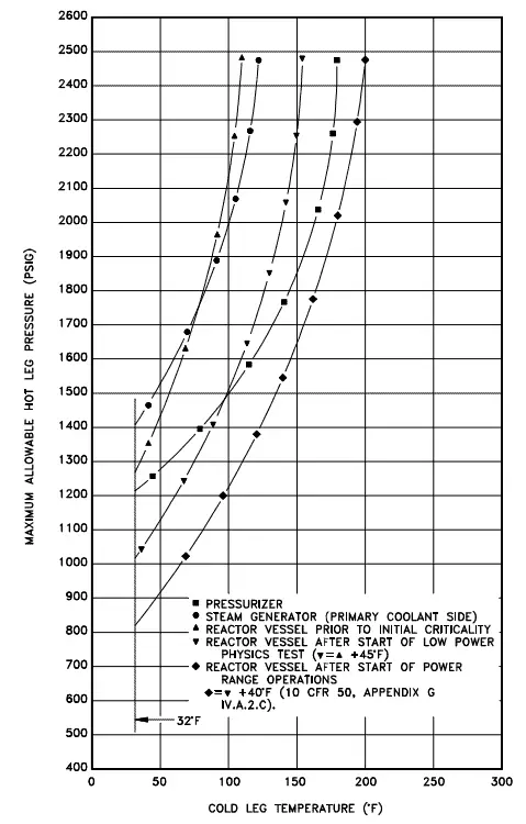
Pressure and temperature limits (P/T) are limiting curves defined in the plant’s Technical Specification. Each P/T limit curve defines an acceptable region for normal operation. 10 CFR 50, Appendix G, requires the establishment of P/T limits for specific material fracture toughness requirements of the pressure boundary materials. The P-T limits are derived on the basis of linear elastic fracture mechanics (LEFM) analyses. In these analyses, the minimum temperature necessary to ensure adequate margins against RPV failure is determined as a function of pressure.
P/T is based on reactor vessel and head stress limitations and the need to preclude reactor vessel and head brittle fracture. The usual use of the curves is operational guidance during heat up or cooldown maneuvering when pressure and temperature indications are monitored and compared to the applicable curve to determine that operation is within the allowable region. The curves used by operations also incorporate instrument error to ensure adequate safety margin. Because of the embrittling effects of neutron irradiation, the MPT curve will shift to the right over core life to account for the increased brittleness or decreased ductility.
Pressurized Thermal Shock – PTS
In general thermal shock is a mechanical load caused by a rapid change of temperature at a certain point. The change in temperature causes stresses on the surface that is in tension, which can encourage crack formation and propagation. Usually, ceramics materials are susceptible to thermal shock, but under some circumstances also, pressurized vessels suffer from thermal shocks. With rapid heating (or cooling) of a thick-walled vessel such as the reactor pressure vessel, one part of the wall may try to expand (or contract) while the adjacent section, which has not yet been exposed to the temperature change, tries to restrain it.
Pressurized Thermal Shock, PTS, means an event or transient in pressurized water reactors (PWRs) causing severe overcooling (thermal shock) concurrent with or followed by significant pressure in the reactor vessel. In this accident scenario, cold water enters a reactor while the vessel is pressurized. This rapidly cools the vessel and places large thermal stresses on the steel. Severe reactor system overcooling events that could be accompanied by pressurization or repressurization of the reactor vessel can result from a variety of causes. Pressure in the reactor system raises the severity of the thermal shock due to the addition of stress from the pressure. Transients, which combine high system pressure and a severe thermal shock, are potentially more dangerous due to the added effect of the tensile stresses on the inside of the reactor vessel wall. PTS-related transients include:
- stuck-open valves in the primary system,
- stuck-open valves in the secondary system,
- small-break loss-of-coolant accidents with subsequent injection of emergency core cooling system (ECCS) water,
- main steam line breaks,
- feedwater line breaks.
The NRC created 10 CFR Part 50.61 and 50.61a – the “PTS rule” and “alternate PTS rule” – to ensure the vessel’s steel remains strong enough to protect the vessel’s integrity. These rules require additional evaluations or other actions if embrittlement reaches certain limits.
RTNDT = RTNDT(U) + M + ΔRTNDT
where:
- RTNDT means the reference temperature for a reactor vessel material under any conditions. For the reactor vessel beltline materials, RTNDT must account for the effects of neutron radiation.
- RTNDT(U) is the reference temperature for a reactor vessel material in pre-service or unirradiated conditions.
- ΔRTNDT is the increase in RTNDT caused by irradiation
- M is a margin added to cover uncertainties in the initial properties, copper and nickel contents, fluence, and calculation procedures. The greater the amounts of copper, nickel, and neutron fluence, the greater the increase.
As long as the fracture toughness of the reactor vessel material is relatively high, such events will not threaten RPV integrity. However, the fracture toughness of reactor vessel materials decreases with exposure to fast neutrons during the life of a nuclear power plant. If the fracture toughness of the vessel material has been reduced sufficiently, severe PTS events could cause the propagation of small flaws that might exist near the inner surface of the vessel. The assumed initial flaw might propagate into a crack through the vessel wall to a sufficient extent to threaten vessel integrity and, therefore, core cooling capability.
While PTS doesn’t affect boiling-water reactors, there are very limited conditions where those vessels could overpressurize at low temperatures.
Special Reference: NUREG-1511, Reactor Pressure Vessel Status Report. U.S. Nuclear Regulatory Commission, Washington, DC, 1994.
Special Reference: DOE FUNDAMENTALS HANDBOOK MATERIAL SCIENCE Volume 2 of 2, DOE-HDBK-1017/2-93, Washington, DC, 1993.
Heatup and Cooldown Rate Limits
The NSSS heat up from Cold Shutdown (MODE 5) to Hot Standby (MODE 3) is performed by reactor coolant pumps which are very powerful (they can consume up to 6 MW each), and therefore, its work together with a decay heat can be used for heating the primary coolant before a reactor startup. To operate the reactor coolant pumps, reactor coolant system pressure must be increased to satisfy net positive suction head requirements. Reactor coolant pumps are started sequentially. The primary plant heat up rate is limited to about 30°C per hour in order to minimize internal stress in the material of the pressure vessel, primary piping, and other components.
Heat up and cooldown rate limits are based upon the impact on the future fatigue life of the plant. The heat up and cooldown limits ensure that the plant’s fatigue life is equal to or greater than the plant’s operational life. Large components such as flanges, the reactor vessel head, and even the reactor vessel itself are the limiting components. Usually, the most limiting component will set the heat up and cooldown rates.
Radiation Damage to Reactor Materials
Nuclear reactors are significant sources of radiation, especially neutron radiation. At power operation, the fission reaction is responsible for the power generated in a nuclear reactor, and the fission reaction rate is proportional to the neutron flux. Fission essentially ceases when a reactor is shut down, but decay energy is still being produced. The energy produced after shutdown is referred to as decay heat. Nuclear reactors are, therefore, sources of various types of radiation, with neutrons being the most important. Each type of radiation interacts in a different way, therefore, we must describe the interaction of particles (radiation as a flow of these particles) separately. For example, charged particles with high energies can directly ionize atoms. On the other hand, electrically neutral particles interact only indirectly but can also transfer some or all of their energies to matter.
This is the key feature of the categorization of radiation sources. They are usually categorized into two general types as follows:
- Charged particles (directly ionizing)
- Beta particles. Beta particles are fast electrons or positrons emitted in nuclear beta decay and energetic electrons produced by any other process. Beta radiation ionizes matter weaker than alpha radiation. On the other hand, the ranges of beta particles are longer and depend strongly on the initial kinetic energy of the particle.
- Heavy charged particles. Heavy charged particles are all energetic ions with a mass of one atomic mass unit or greater, such as protons, alpha particles (helium nuclei), or fission fragments. The stopping power of most materials is very high for alpha particles and heavy-charged particles. Therefore alpha particles have very short ranges. On the other hand, they produce massive ionization of surrounding matter.
- Neutral particles (indirectly ionizing)
- Gamma radiation (electromagnetic radiation). Gamma rays ionize matter primarily via indirect ionization. Gamma rays are very penetrating. On the other hand, their ionization is not so intense as for charged particles. Although a large number of possible interactions are known, there are three key interaction mechanisms with the matter.
- Neutrons. Neutrons can be emitted by nuclear fission or by the decay of some radioactive atoms. Neutrons have no net electric charge, therefore, they cannot be affected or stopped by electric forces. Neutrons ionize matter only indirectly, which makes neutrons a highly penetrating type of radiation. Neutrons scatter with heavy nuclei very elastically. Heavy nuclei very hard slow down a neutron, let alone absorb a fast neutron. An absorption of neutrons (one would say shielding) causes initiation of certain nuclear reactions (capture, rearrangement, or even fission), which is accompanied by a number of other types of radiation. In short, only neutrons make matter radioactive. Therefore, with neutrons, we have to shield also the other types of radiation.
Radiation-induced Crystallographic Defects
Materials in nuclear service are subjected to various types of radiation. Some of these can cause significant damage to the crystalline structure of materials. Nuclear radiation focuses large amounts of energy on highly localized areas. Damage is caused by the interaction of this energy with the nuclei and/or orbiting electrons.
As was written, charged particles with high energies can directly ionize atoms, or they can cause the excitation of surrounding electrons. The ionization and excitation dissipate much of the energy of heavier charged particles and do very little damage. This is because electrons are relatively free to move and are soon replaced. The net effect of beta and gamma radiation on metal is to generate a small amount of heat. Heavier particles, such as protons, alpha-particles, fast neutrons, and fission fragments, will usually transfer sufficient energy through elastic or inelastic collisions to remove nuclei from their lattice (crystalline) positions. This addition of vacancies and interstitial atoms causes property changes in metals.
In general, the effects of greatest interest can be described by the following groupings:
- Vacancies or Knock-ons. Vacancy defects result from a missing atom in a lattice position. The stability of the surrounding crystal structure guarantees that the neighboring atoms will not simply collapse around the vacancy. This can be caused by the direct interaction of a high-energy neutron or a fission fragment. If a target or struck nucleus gains about 25 eV of kinetic energy (25 eV to 30 eV for most metals) in a collision with a radiation particle (usually a fast neutron), the nucleus will be displaced from its equilibrium position in the crystal lattice. During lengthy irradiation (for large values of the neutron fluence), many of the displaced atoms will return to normal (stable) lattice sites (that is, partial annealing occurs spontaneously).
- Interstitials. Interstitial defects result from an impurity located at an interstitial site or one of the lattice atoms being in an interstitial position instead of being at its lattice position. An interstitial is formed when an atom, which is knocked out from its position, comes to rest at some remote point.
- Ionization. Ionization is caused by the removal of electrons from their electronic shells and has the effect of changing the chemical bonds of molecules. In metal, ionization does not cause dramatic changes in the material’s properties. This is due to free electrons, which are typical only for metallic bonds.
- Thermal and Displacement Spikes. Thermal and displacement spikes can cause distortion that is frozen as stress in the microscopic area. These spikes can cause a change in the material’s properties. This term identifies localized high-temperature domains caused by the deposition of energy from neutrons and fission fragments. A displacement spike occurs when many atoms in a small area are displaced by a knock-on (or cascade of knock-ons). A 1 MeV neutron may affect approximately 5000 atoms, making up one of these spikes. The presence of many displacement spikes changes the properties of the metal being irradiated, such as increased hardness and decreasing ductility.
- Impurity Atoms. The capture of neutrons and nuclear reactions induced by various radiations has the effect of transmuting an atom into an element that is foreign to the material.
- Radiation-Induced Creep. In nuclear reactors, many metal components are subjected simultaneously to radiation fields, elevated temperatures, and stress. Metal under stress at elevated temperature exhibits the phenomenon of creep, i.e. the gradual increase in strain with time. The creep of metal components at reactor operating temperatures becomes faster when they are exposed to a radiation field.
Neutrons with sufficient energy can disrupt materials’ atomic arrangement or crystalline structure. The influence of structural damage is most significant for metals because of their relative immunity to damage by ionizing radiation. Pressurized-water reactors operate with a higher rate of neutron impacts, and their vessels, therefore, tend to experience a greater degree of embrittlement than boiling-water reactor vessels. Many pressurized-water reactors design their cores to reduce the number of neutrons hitting the vessel wall. This slows the vessel’s embrittlement. The NRC’s regulations address embrittlement in 10 CFR Part 50, Appendix G, “Fracture Toughness Requirements,” and Appendix H, “Reactor Vessel Material Surveillance Program Requirements.” Since the reactor pressure vessel is considered irreplaceable, neutron irradiation embrittlement of pressure vessel steels is a key issue in the long-term assessment of structural integrity for life attainment and extension programs.
Radiation damage is produced when neutrons of sufficient energy displace atoms (especially in steels at operating temperatures 260 – 300°C) that result in displacement cascades which produce large numbers of defects, both vacancies, and interstitials. Although the inside surface of the RPV is exposed to neutrons of varying energies, the higher energy neutrons, those above about 0.5 MeV, produce the bulk of the damage. In order to minimize such material degradation type and structure of the steel must be appropriately selected. Today it is known that the susceptibility of reactor pressure vessel steels is strongly affected (negatively) by the presence of copper, nickel, and phosphorus.
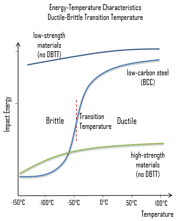 As was written, the distinction between brittleness and ductility isn’t readily apparent, especially because both ductility and brittle behavior are dependent not only on the material in question but also on the temperature (ductile-brittle transition) of the material. The effect of temperature on the nature of the fracture is of considerable importance. Many steels exhibit ductile fracture at elevated temperatures and brittle fracture at low temperatures. The temperature above which material is ductile and below which it is brittle is known as the ductile-brittle transition temperature (DBTT), nil ductility temperature (NDT), or nil ductility transition temperature. This temperature is not precise but varies according to prior mechanical and heat treatment and the nature and amounts of impurity elements. It can be determined by some form of drop-weight test (for example, the Charpy or Izod tests).
To minimize neutron fluence:
- Radial neutron reflectors are installed around the reactor core. Neutron reflectors reduce neutron leakage, and therefore, they reduce the neutron fluence on a reactor pressure vessel.
- Core designers design low leakage loading patterns in which fresh fuel assemblies are not situated in the peripheral positions of the reactor core.
If the metal is heated to elevated temperatures after irradiation (a form of annealing), it is found that the strength and ductility return to the same values as before irradiation. This means that radiation damage can be annealed out of metal.
See also: Ductile-brittle Transition Temperature
See also: Irradiation Embrittlement
See also: Thermal Annealing
Reactor Vessel Material Surveillance Program
Reactor vessel surveillance programs provide information on the effect of radiation on vessel materials under operating conditions. The reactor vessel surveillance program utilizes capsules located on the vessel wall directly opposite the center of the core. The capsules contain reactor vessel steel specimens obtained during vessel fabrication and are withdrawn periodically from the reactor vessel. The surveillance capsules must be located near the inside vessel wall in the beltline region so that the material specimens duplicate, to the greatest degree possible, the neutron spectrum, temperature history, and maximum neutron fluence as experienced at the reactor vessel’s inner surface. A specimen capsule containing specimens for use in Charpy V-notch, tensile, and fracture mechanics tests can be removed from the reactor during normal refueling periods.
The Charpy V-notch (CVN) technique is most commonly used. The Charpy V-notch test uses a notched sample of the defined cross-section. We use notch toughness for these dynamic loading conditions and when a notch is present. Charpy and Izod impact tests are used to measure this parameter, which is important in assessing the ductile-to-brittle transition behavior of a material. Similarly, as for tensile toughness, notch toughness is measured in units of joule per cubic meter (J·m−3) in the SI system, but in this case, we are measuring the area at the notch position.
There can also be special dosimeters, including pure nickel, copper, iron, aluminum-cobalt, or uranium-238, which can be placed in spacers specially drilled to contain the dosimeters.
According to 10 CFR 50 Appendix H, no material surveillance program is required for reactor vessels for which it can be conservatively demonstrated by analytical methods applied to experimental data and tests performed on comparable vessels, making appropriate allowances for all uncertainties in the measurements, that the peak neutron fluence at the end of the design life of the vessel will not exceed 1017 n/cm2 (E>1 MeV).
Special Reference: NUREG-1511, Reactor Pressure Vessel Status Report. U.S. Nuclear Regulatory Commission, Washington, DC, 1994.
Reactor Pressure Vessel Annealing
During the operation of a nuclear power plant, the material of the reactor pressure vessel and the material of other reactor internals are exposed to neutron radiation (especially to fast neutrons >0.5MeV), which results in localized embrittlement of the steel and welds in the area of the reactor core. This phenomenon, known as irradiation embrittlement, results in:
- Steadily increase in DBTT. It is not likely that the DBTT will approach the normal operating temperature of the steel. However, there is a possibility that when the reactor is shut down or during an abnormal cooldown, the temperature may fall below the DBTT value while the internal pressure is still high.
- Drop in the upper shelf fracture energy. Radiation effects are also manifested by a drop in the upper shelf fracture energy and a decrease in fracture toughness.
All these effects must be monitored by plant operators. Therefore nuclear regulators require that a reactor vessel material surveillance program be conducted in water-cooled power reactors.
Once a material of RPV is degraded by radiation embrittlement (e.g., a significant increase in Charpy ductile‐brittle transition temperature or reduction of fracture toughness), thermal annealing of the RPV is the only way to recover the RPV material toughness properties.
According to 10 CFR 50.66 – Requirements for thermal annealing of the reactor pressure vessel:
„For those light water nuclear power reactors where neutron radiation has reduced the fracture toughness of the reactor vessel materials, thermal annealing may be applied to the reactor vessel to recover the fracture toughness of the material.“
Thermal annealing („dry“ method) of the reactor pressure vessel is a method by which the pressure vessel (with all reactor internals removed) is heated up to some temperature (usually between 420 – 460 °C) by use of an external heat source (electrical heaters, hot air), held for a given period (e.g., 100 – 200 hours) and then slowly cooled. The annealing equipment is usually a ring‐shaped furnace with heating elements on its external surface. The power output of installed heaters may reach up to 1 MWe. It was shown that for the specially fabricated materials, the upper shelf recovered 100 % after 24 hours of annealing and more rapidly than transition temperature. Annealing for 168 hours recovered 90 % of the transition temperature shift.
Wet Annealing
There is also a possibility of the so‐called “wet” annealing method, which was applied in the USA and Belgium. The annealing at that temperature of ~340 °C was reached without external heating but by increasing the coolant temperature achieved by the energy of the circulating pumps of the primary circuit. This type of annealing provides only partial recovery for the material due to the limitation in maximum temperature.
Special Reference: Annealing and re-embrittlement of reactor pressure vessel materials. AMES report N.19; ISSN 1018-5593. European Communities, 2008.
Corrosion
Corrosion is the deterioration of a material due to chemical interaction with its environment. It is a natural process in which metals convert their structure into a more chemically-stable form, such as oxides, hydroxides, or sulfides. Corrosion is of primary concern in nuclear reactor plants. Corrosion occurs continuously throughout the reactor plant, and every metal is subject to it. Even though this corrosion cannot be eliminated, it can be controlled.
In March 2002, while the Davis-Besse nuclear reactor in Ohio was responding to the 2001 Bulletin, the plant identified a football-sized cavity in the reactor vessel head. The cavity was next to a cracked, leaking nozzle in an area of the vessel head covered with deposits from years of leaks. A few days after the discovery, the NRC issued a Confirmatory Action Letter to the plant owner, First Energy Nuclear Corporation. The letter ensured the plant would remain shut down until the company evaluated and resolved the vessel head damage. Later analysis concluded the cracked nozzle leaked borated water, which created boric acid that corroded the vessel head’s steel and created the cavity.
See also: Corrosion
Materials for Nuclear Fuel
 In PWRs, the reactor core consists of assemblies of fuel rods featuring a zirconium alloy cladding, holding uranium oxide pellets (with uranium enriched to ~ 4% U-235) or MOX pellets (mixed uranium-plutonium oxides [(U, Pu)O2], with a Pu content of 5–10%). Fuel fabrication is the final step of the front end of the nuclear fuel cycle. In this step, a complete fuel assembly is fabricated. Since a fuel assembly consists of several structural parts, then this step may be processed at different locations, and these parts may also be prefabricated.
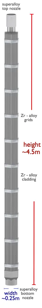
- Fuel Pellets. Most of PWRs use uranium fuel, which is in the form of uranium dioxide. Uranium dioxide is a black semiconducting solid with very low thermal conductivity. On the other hand, uranium dioxide has a very high melting point and has well-known behavior. The UO2 is pressed into pellets. These pellets are then sintered into the solid cylinder (with a height and diameter of about 1 centimeter, the height being greater than the diameter). The dimensions of the fuel pellets and other components of the fuel assembly are precisely controlled to ensure consistency in the characteristics of the fuel. These pellets are then loaded and encapsulated within a fuel rod (a metallic cladding tube), which is made of zirconium alloys due to its very low absorption cross-section (unlike stainless steel). The surface of the tube, which covers the pellets, is called fuel cladding. Fuel rods are the base element of a fuel assembly. Fuel rods have the purpose of containing fission products, ensuring mechanical support for the pellets, and allowing the heat removal to the coolant fluid of the heat generated by nuclear reactions. A typical fuel rod has a length of some 4 m, with a diameter of around 1 cm.
- Material: Uranium Dioxide
- Fuel Cladding. Zirconium is a lustrous, grey-white, strong transition metal that resembles hafnium and, to a lesser extent, titanium. Zirconium is mainly used as a refractory and opacifier, although small amounts are used as an alloying agent for its strong resistance to corrosion. Zirconium alloy (e.g., Zr + 1%Nb) is widely used as a cladding for nuclear reactor fuels. The desired properties of these alloys are a low neutron-capture cross-section and resistance to corrosion under normal service conditions. Zirconium alloys have lower thermal conductivity (about 18 W/m.K) than pure zirconium metal (about 22 W/m.K).
- Material: Zirconium Alloy
- Top Nozzle and Bottom Nozzle. A PWR fuel assembly comprises a bottom nozzle into which rods are fixed through the lattice, and to finish the whole assembly, it is ended by a top nozzle. There are spacing grids between these nozzles. These grids ensure an exact guiding of the fuel rods. The bottom and top nozzles are heavily constructed as they provide much of the mechanical support for the fuel assembly structure. The top nozzle ensures the assembly handling function. The bottom nozzle provides mechanical support for the fuel assembly structure. The bottom nozzle features a debris mitigation device to catch traveling foreign bodies, which had formed, at one time, the chief cause of cladding failure.
- Material: Stainless Steel
- Material: Superalloys – Inconel
- Spacing Grid. Ensures an exact guiding of the fuel rods. Spacing grids are welded onto the guide tubes and ensured, by means of springs and dimples, fuel rod support, and spacing. They may carry vanes, allowing improved mixing of fluid streams, thus enhancing the assembly’s thermal-hydraulic performance.
- Material: Superalloys – Inconel
- Material: Zirconium Alloy
- Guide thimble Tubes. A vacant tube for control rods or incore instrumentation. The absorber rods in the control clusters slide within the guide tubes.
- Material: Zirconium Alloy
- Instrumentation Tube. An instrumentation tube is a vacant tube only for incore instrumentation, such as the incore neutron flux monitoring system.
- Material: Zirconium Alloy
The fuel assembly constitutes the base element of the nuclear reactor core. The reactor core (PWR type) contains about 157 fuel assemblies (depending on the reactor type). Western PWRs use a square lattice arrangement, and assemblies are characterized by the number of rods they contain, typically 17×17 in current designs. The enrichment of fuel rods is never uniform. The enrichment is differentiated in the radial direction but also in the axial direction. This arrangement improves power distribution and improves fuel economy.
Material Problems of Nuclear Fuels
Loss of Tightness of Fuel Cladding
Cladding prevents radioactive fission products from escaping the fuel matrix into the reactor coolant and contaminating it. The emergence of a leak in that cladding results in:
- the transport of specific chemical elements (fission products) that are stable and radioactive (iodine, xenon, krypton…) into the reactor’s primary circuit
- deposits of long-lived isotopes (cesium, strontium, technetium…), or even, in exceptional circumstances, of alpha emitters onto the piping of the primary circuit or of ancillary circuits
- an increase in the overall level of irradiation for that circuit from the level already due to activation products (corrosion products, e.g., cobalt, chromium, iron in particular)
A leak thus poses a major challenge in operational terms for a power plant operator since it has a direct bearing on the level of radiological exposure workers are subjected to when running the plant or carrying out maintenance. Although fuel failures have rarely been a safety-related issue, their impact on plant operational costs due to:
- premature fuel discharge,
- following cycle shortening,
- possible unscheduled outages,
- increased spent fuel volume
One of the necessary steps to reach the zero defect goal is to understand the root causes of the failures and their mechanisms so that some corrective actions can be implemented, either through improvements in fuel design and fabrication by fuel suppliers or operational changes, such as reduced power maneuvering.
Special Reference: CEA, Nuclear Energy Division. Nuclear Fuels, ISBN 978-2-281-11345-7
Fuel Failure Mechanisms
Various fuel failure root causes have been identified in the past. These causes were predominantly fabrication defects or fretting in the early days of PWR and BWR operations. The following list is not complete. Failure mechanisms are also are typical for certain reactor and fuel designs. It must also be noted that many the fuel failure causes were never identified and remain unknown.
- Fretting. Fretting was one of the main failure mechanisms in the early dates of PWR and BWR operations, and it typically has two variants.
- Debris fretting. Debris fretting can be caused by any debris (foreign material – usually metallic) that can enter the fuel bundle and potentially become lodged between the spacer grid and a fuel rod. Fretting wear of fuel cladding can result in cladding penetration.
- Grid-to-rod fretting. Grid-to-rod fretting arises from the vibration of the fuel element generated by the high coolant
velocity through the spacing grid. Spacing grids are welded onto the guide tubes and ensured, by means of springs and dimples, fuel rod support, and spacing. High coolant velocity can cause the rod to rub against the part of the spacer grid
that holds it. This type of cladding wear can be minimized by proper design of the spacing grid. Baffle-jetting is usually grouped under grid-to-rod fretting.
- Pellet-cladding interaction (PCI). Failures due to PCI are typical for power changes, rod movement, and plant startup. They usually occur within a few hours or days following a power ramp or control rod movement, and this results especially in startup ramp rate restrictions.
- Dryout. In BWRs, when the heat flux exceeds a critical value (CHF – critical heat flux), the flow pattern may reach the dry-out conditions (a thin film of liquid disappears). The heat transfer from the fuel surface into the coolant deteriorates, resulting in a drastically increased fuel surface temperature. This phenomenon can cause the failure of the affected fuel rod.
- Fabrication defects
- End-plug weld defects.
- Cladding creeps collapse. Cladding collapse can be caused by densification of the fuel pellets forming axial gaps in the pellet column, resulting in collapse from outer pressure. Since creep is time-dependent, full collapse typically occurs at higher burnup. This type of failure can be eliminated through the use of pellets with moderate densification and pre-pressurization of rods.
- Missing pellet surface
- Internal Hydriding. Inadvertent inclusion of hydrogen-containing materials inside a fuel rod can result in hydriding and thus embrittlement of fuel cladding. Hydrogen sources were mainly residual moisture or organic contamination in fuel pellets/rods. This cause of failure has been practically eliminated through improved manufacturing.
- Crud-induced corrosion. Crud-induced corrosion failures are either due to abnormally high heat flux exceeding heat flux or burnup corrosion limits or to water chemistry problems leading to excessive crud deposits. In BWRs, crud-induced corrosion was one of the major causes of fuel failure in the 1980s.
- Delayed hydride cracking (DHC). Delayed hydride cracking is time-dependent crack initiation and propagation through fracture of hydrides that can form ahead of the crack tip. This type of failure can be initiated by long cracks at the outer surface of the cladding, which can propagate in an axial/radial direction. This failure mechanism may potentially limit high burnup
operation. - Fuel handling damages
See also: IAEA, Review of fuel failures in water-cooled reactors. No. NF-T-2.1. ISBN 978–92–0–102610–1, Vienna, 2010.
High-Temperature Steam Oxidation of Zirconium Alloys
At high temperatures, the exothermic reaction of Zr-base alloys with steam is much more intensive and hazardous for the safety of nuclear power plants during accidents like a loss-of-coolant accident (LOCA). The main problem of high-temperature oxidation is that zirconium cladding rapidly reacts with water steam at high temperatures. The oxidation kinetics of relevant zirconium alloys appears to be parabolic in the temperature range of 1000-1500°C for many Zr-based alloys. Above 1577°C, the oxide layer transforms from tetragonal to cubic, and the oxidation rate even increases. Moreover, the oxidation of zirconium by water is accompanied by a release of hydrogen gas. This oxidation is accelerated at high temperatures, e.g., inside a reactor core, if the fuel assemblies are no longer completely covered by liquid water and insufficiently cooled. Metallic zirconium is then oxidized by water/steam to form hydrogen gas according to the following redox reaction:
Zr + 2H2O→ZrO2 + 2H2 (Q = 190 kJ/mol; Baker and Just)
See also: High-Temperature Steam Oxidation of Zirconium Alloys
Nuclear Fuel Melting
The thermal conductivity of uranium dioxide is very low when compared with metal uranium, uranium nitride, uranium carbide, and zirconium cladding material. Thermal conductivity is one of the parameters, which determine the fuel centerline temperature. This low thermal conductivity can result in localized overheating in the fuel centerline; therefore, this overheating must be avoided. Overheating of the fuel is prevented by maintaining the steady state peak linear heat rate (LHR) or the Heat Flux Hot Channel Factor – FQ(z) below the level at which fuel centerline melting occurs. Expansion of the fuel pellet upon centerline melting may cause the pellet to stress the cladding to the point of failure.
Although the melting point of UO2 is over 2,800°C, fuel is usually operated at a much lower peak centerline temperature (less than 1,400°C). This provides enough margin for fuel melting and loss of fuel integrity. In general, fuel melting must be excluded for condition III and condition IV accidents. But the Fukushima Daiichi nuclear disaster in 2011 raised the safety problem of nuclear power plants to a new level worldwide. It is difficult to predict these events and all other beyond-design-basis accidents and prepare for them due to their extreme rarity. Under these infrequent circumstances, the plant may be unable to operate safely. Reduction in the safety margin of a plant can cause catastrophic failures such as meltdowns.
In the case of nuclear fuel melting, it is necessary to distinguish in which event the fuel melting temperature is reached. Fuel melting can occur:
- Slow fuel rod overpower. In the event of an increase in fuel overpower that is slow compared to the rate of heat transfer through the fuel, melting occurs only on a local scale.
- Loss of ultimate heat sink. In the event of loss of reactor coolant, the rod’s power decreases, and the fuel temperature is only a few tens of degrees Celsius higher than the cladding temperature.
- RIA accidents. In these accidents, the large and rapid deposition of energy in the fuel can result in melting, fragmentation, and dispersal of fuel.
Reactor Core Melt Accident
A reactor core melt accident is an event or sequence of events that result in the melting of part of the fuel in the reactor core. Although this event is very unlikely, it cannot be ruled out. There are many and many barriers that have to be breached. Especially, common (usually 3×100%) failure of the Emergency Core Cooling System (ECCS) must occur after severe loss of coolant accident.
This type of accident is known as a nuclear meltdown (core meltdown). However, this is not officially defined by the International Atomic Energy Agency or the Nuclear Regulatory Commission. The core melt accident is a severe nuclear reactor accident that results in core damage from overheating. It occurs when the heat generated by a nuclear reactor exceeds the heat removed by the cooling systems to the point where at least one nuclear fuel element exceeds its melting point. The heat causing the melting of a reactor may originate from the nuclear chain reaction, but more commonly, decay heat of the fission products contained in the fuel rods is the primary heat source.
Suppose the reactor core remains dry for a considerable length of time. In that case, the temperature of the fuel rods rises and may locally reach levels that cause significant and irreversible core degradation. The mechanisms of this degradation are both chemical and mechanical. Depending on the local temperature levels, degradation may result in more or less severe hydrogen production, fission product (FP) release, molten corium formation, and propagation towards the lower head.
Special reference: Nuclear Power Reactor Core Melt Accidents ISBN: 978-2-7598-1835-8, IRSN 2015.
Corium
Corium, also called fuel-containing material (FCM), is a lava-like material created in the core of a nuclear reactor during a meltdown accident. It consists of:
- the mixture of nuclear fuel and oxidized zirconium clad,
- fission products,
- control rods,
- structural materials from the affected parts of the reactor, products of their chemical reaction with air, water, and steam,
- and, if the reactor vessel is breached, molten concrete from the floor of the reactor room.
If the temperature reaches the melting point of UO2, a fuel usually degrades from the center of the core. Due to the formation of the eutectic liquids, the melting temperature may be several hundred degrees below that of the UO2 melting point (3100 K). Zirconium from fuel clad, together with other metals, reacts with water and produces zirconium dioxide and hydrogen. The production of hydrogen is a major danger in reactor accidents. As the eutectic molten mass increases, the corium pool may be formed and expands axially and radially in the core until it reaches either the baffle or the core support plate. At this moment, the corium flows into the lower head. The degradation may ultimately result in very different configurations in the core simultaneously, ranging from intact or barely degraded rods to forming a corium pool or a bed of debris.
In all cases, the corium gradually evaporates the water present in the lower head. Suppose there is no additional water supply and the debris configuration is such that it cannot be cooled effectively. In that case, the materials’ temperature gradually rises until it reaches the melting point of the steel structures (plates, tubes, etc.) located in the lower head. In the case of adequate cooling of the corium, it can solidify, and the damage is limited to the reactor. However, in the absence of adequate cooling, corium may melt through the reactor vessel and flow out or be ejected as a molten stream by the pressure inside the reactor vessel.
However, core reflooding may not be beneficial in all conditions. The following phenomena can occur during reflooding:
- massive steam generation, with hydrogen production and an increase in reactor
- coolant system pressure;
- steam explosion through corium-water interaction;
- continuation of the core melt, despite water inflow;
- faster release of fission products.
In the event of reactor-vessel failure during a core melt accident, the corium resulting from this core melt and the melting of internal structures will pour onto the reactor pit basement. The molten core-concrete interaction (MCCI) is one of the important phenomena that may lead to late containment failure by basement penetration in a hypothetical severe accident of light water reactors (LWRs). The process is driven by the high initial temperature of the molten corium and the decay heat generated inside the melt by the radioactive decay of the fission product. The progression of MCCI takes paramount importance and plays a key role to threaten the integrity of the containment, the last barrier of fission products.
In-vessel Retention
With regards to the safety of the Nuclear Power Plants (NPP) in case of a severe nuclear accident, one of the main challenges associated is the retention of the molten nuclear fuel and reactor internals, called corium, within the Reactor Pressure Vessel (RPV). One of the ways of cooling corium within the RPV is by cooling the vessel from the outside. The in-vessel retention can be achievedfully floodingg of the reactor cavity to cool the external wall of the lower head, thereby avoiding structural failure by creep rupture. This strategy is termed as In-Vessel Retention (IVR). In the case of the In-Vessel Retention (IVR) strategy, it is expected that the corium pool will be surrounded by an oxide crust, which will be in contact with molten steel from the top of the pool as well as from the sides of the vessel. The application of this approach to large power reactors is not trivial because of the relatively short time between the detection of core melting and the lower head failure.
Enthalpy of Nuclear Fuel
Enthalpy of nuclear fuel is also used as an acceptance criterion in very specific types of accidents, known as reactivity-initiated accidents (RIA), such as Rod Ejection Accidents. RIAs consist of postulated accidents involving a sudden and rapid positive reactivity insertion. As a result of rapid power excursion, fuel temperatures rapidly increase, prompting fuel pellet thermal expansion. The power excursion is initially mitigated by the fuel temperature coefficient (or Doppler feedback), which will be the first feedback that will compensate for the inserted positive reactivity.
In these accidents, the large and rapid deposition of energy in the fuel can result in melting, fragmentation, and dispersal of fuel. The mechanical action associated with fuel dispersal can be sufficient to destroy the fuel’s cladding and rod-bundle geometry and produce pressure pulses in the primary system. The expulsion of hot fuel into water has the potential to cause rapid steam generation and these pressure pulses, which could damage nearby fuel assemblies. Limits on specific fuel enthalpy are used because the experimental tests show that the degree of fuel rod damage correlates well with the peak value of fuel pellet-specific enthalpy.
Materials for Steam Turbines
Most the nuclear power plants operate a single-shaft turbine-generator that consists of one multi-stage HP turbine and three parallel multi-stage LP turbines, the main generator, and an exciter. HP Turbine is usually a double-flow reaction turbine with about 10 stages with shrouded blades and produces about 30-40% of the gross power output of the power plant unit. LP turbines are usually double-flow reaction turbines with about 5-8 stages (with shrouded blades and free-standing blades for the last 3 stages). LP turbines produce approximately 60-70% of the gross power output of the power plant unit. Each turbine rotor is mounted on two bearings, i.e., double bearings between each turbine module. The range of alloys used in steam turbines is relatively small, partly because of the need to ensure a good match of thermal properties, such as expansion and conductivity, and partly because of the need for high-temperature strength at an acceptable cost.
- Material for turbine rotors. The rotors of steam turbines are usually made of low-alloy steel. The role of the alloying elements is to increase hardenability to optimize mechanical properties and toughness after heat treatment. The rotors are required to handle the highest steam conditions; therefore, the alloy most commonly used is CrMoV steel.
- Material for the casing. The casings of steam turbines typically are large structures with complex shapes that must provide the pressure containment for the steam turbine. Because of the size of these components, their cost has a strong impact on the overall cost of the turbine. The materials used currently for inner and outer casings are usually low-alloy CrMo steels (e.g., the 1-2CrMo steel). For higher temperatures, cast 9CrMoVNb alloys are conside be adequate in terms of strength.
- Material of turbine blading. For gas turbines, the turbine blades are often the limiting component. The highest temperature in the cycle occurs at the end of the combustion process, and it is limited by the maximum temperature that the turbine blades can withstand. As usual, metallurgical considerations (about 1700 K) place upper limits on thermal efficiency. Therefore turbine blades often use exotic materials like superalloys and many differcooling methodsling, such as internal air channels, boundary layer cooling, and thermal barrier coatings. The development of superalloys in the 1940s and new processing methods, such as vacuum induction melting in the 1950s, greatly increased the temperature capability of turbine blades. Modern turbine blades often use nickel-based superalloys that incorporate chromium, cobalt, and rhenium.
- Steam turbine blades are not exposed to such high temperatures, but they must withstand an operation with two-phase fluid. The high content of water droplets can cause rapid impingement and erosion of the blades, which occurs when condensed water is blasted onto the blades. For example, condensate drains are installed in the steam piping leading to the turbine to prevent this. Another challenge for engineers is the design of blades for the last stage of the LP turbine. These blades must be (due to the high specific volume of steam) very long, which induces enormous centrifugal forces during operation. Therefore, turbine blades are subjected to stress from centrifugal force (turbine stages can rotate at tens of thousands of revolutions per minute (RPM), but usually at 1800 RPM) and fluid forces that can cause a fracture, yielding, or creep failures.
Material Problems of Turbines
Creep
Creep, also known as cold flow, is the permanent deformation that increases with time under constant load or stress. It results due to long time exposure to large external mechanical stress within the limit of yielding and is more severe in materials that are subjected to heat for a long time. The deformation rate is a function of the material’s properties, exposure time, exposure temperature, and the applied structural load. Creep is very important if we use materials at high temperatures. Creep is very important in the power industry and is of the highest importance in designing jet engines. Time to rupture is the dominant design consideration for many relatively short-life creep situations (e.g., turbine blades in military aircraft). Of course, for its determination, creep tests must be conducted to the point of failure, termed creep rupture tests.
Erosion Corrosion
Erosion corrosion is the cumulative damage induced by electrochemical corrosion reactions and mechanical effects from relative motion between the electrolyte and the corroding surface. Erosion can also occur in combination with other forms of degradation, such as corrosion, and this is referred to as erosion-corrosion. Erosion corrosion is a material degradation process due to the combined effect of corrosion and wear. Nearly all flowing or turbulent corrosive media can cause erosion corrosion. The mechanism can be described as follows:
- mechanical erosion of the material, or protective (or passive) oxide layer on its surface,
- enhanced corrosion of the material if the corrosion rate of the material depends on the thickness of the oxide layer.
Erosion corrosion is found in the systems such as piping, valves, pumps, nozzles, heat exchangers, and turbines. Wear is a mechanical material degradation process occurring on rubbing or impacting surfaces, while corrosion involves chemical or electrochemical reactions of the material. Corrosion may accelerate wear, and wear may accelerate corrosion.
Steam Oxidation
Steam oxidation behavior is directly linked to implementing ultra-supercritical steam power generation for improved efficiencies and reduced CO2 emissions. Higher temperature means higher efficiency; however, higher corrosion rates occur in a steam atmosphere when ferritic, ferritic‐martensitic, or medium Cr–Ni steels are used.
The materials that were developed over 50–60 years ago are no longer currently suitable for ultra-supercritical regimes due to poor corrosion resistance and inadequate high‐temperature creep and strength properties. These technologies require advanced austenitic steels and nickel (Ni)‐based alloys with superior steam oxidation resistance.
Fatigue
In materials science, fatigue is the weakening of a material caused by cyclic loading, resulting in progressive, brittle, and localized structural damage. Once a crack has been initiated, each loading cycle will grow the crack a small amount, even when repeated alternating or cyclic stresses are of an intensity considerably below the normal strength. The stresses could be due to vibration or thermal cycling. Fatigue damage is caused by:
- simultaneous action of cyclic stress,
- tensile stress (whether directly applied or residual),
- plastic strain.
If any of these three is not present, a fatigue crack will not initiate and propagate. The majority of engineering failures are caused by fatigue.
Although the fracture is of a brittle type, it may take some time to propagate, depending on both the intensity and frequency of the stress cycles. Nevertheless, there is little warning before failure if the crack is not noticed. The number of cycles required to cause fatigue failure at a particular peak of stress is generally quite large, but it decreases as the stress is increased. For some mild steels, cyclical stresses can be continued indefinitely provided the peak stress (sometimes called fatigue strength) is below the endurance limit value. The type of fatigue of most concern in nuclear power plants is thermal fatigue. Thermal fatigue can arise from thermal stresses produced by cyclic changes in temperature. Large components like the pressurizer, reactor vessel, and reactor system piping are subject to cyclic stresses caused by temperature variations during reactor startup, changes in power level, and shutdown.