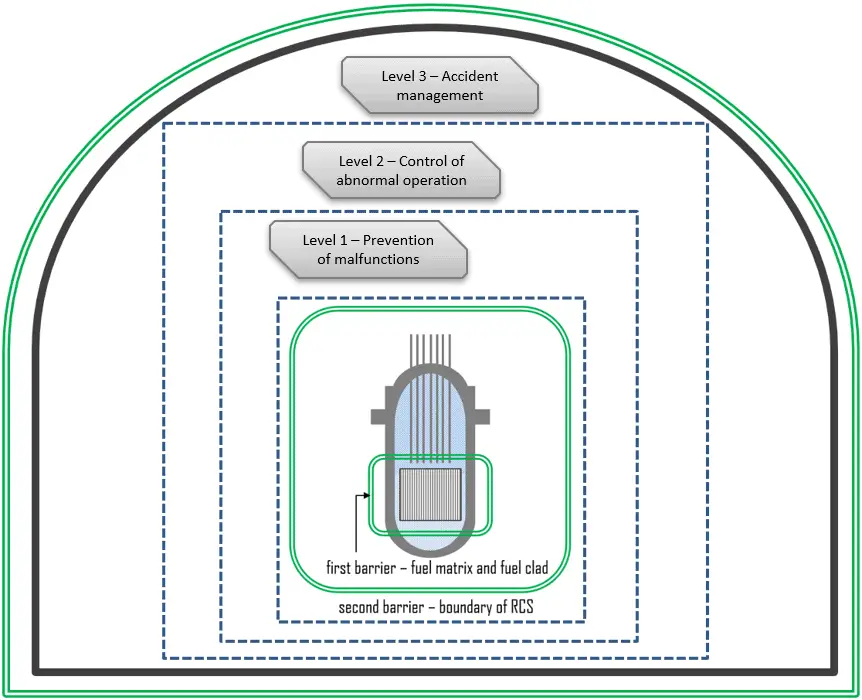
Design bases accidents and comprehensive accident management constitute the third level of defense-in-depth. Despite provisions for prevention, accident conditions may occur. Engineered safety features and protection systems are provided to prevent evolution towards severe accidents and confine radioactive materials within the containment system. The measures are taken at this level aim to prevent core damage in particular. Design and operating procedures are also aimed at maintaining the effectiveness of the barriers, especially the containment. For example, the emergency core cooling system (ECCS) is provided to mitigate the consequences of a loss-of-coolant accident (LOCA), even though the first level of defense makes such an occurrence highly unlikely.
Design bases accident is a postulated accidents in which a nuclear facility must be designed and built to withstand without losing the systems, structures, and components necessary to ensure public health and safety. Design bases accidents are unanticipated conditions of operation (i.e., not expected to occur during the life of the nuclear power unit), but they cannot be excluded. Design bases accidents are also known as Condition III and IV events.
A set of accidents to be considered in the design shall be derived from postulated initiating events to establish the boundary conditions for the nuclear power plant to withstand without acceptable limits for radiation protection being exceeded.
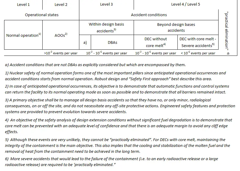
A primary objective shall be to manage all design basis accidents so that they have no, or only minor, radiological consequences, on or off the site, and do not necessitate any offsite protective actions.
The following are some examples of postulated accidents in PWRs and BWRs of current designs:
- Major rupture of a pipe containing reactor coolant up to and including double-ended rupture of the largest pipe in the reactor coolant pressure boundary (PWR and BWR)
- Ejection of a control rod assembly (PWR)
- Control rod drop accident (BWR)
- Major secondary system pipe rupture up to and including double-ended rupture (PWR and BWR)
- Single reactor coolant pump locked rotor (PWR)
- Seizure of one recirculation pump (BWR)
Postulated Initiating Event
A postulated initiating event, or PIE, is defined as an “identified event that leads to anticipated operational occurrences or accident conditions and its consequential failure effect.”
For certain plant designs, the postulated initiating events shall be identified based on engineering judgment and a combination of deterministic and probabilistic assessments.
Postulated initiating events shall be identified and grouped based on their frequency of occurrence at the nuclear power plant. Therefore, there are two groups of PIEs:
- Anticipated operational occurrences. Anticipated operational occurrences, AOOs, refer to the events that are categorized in Regulatory Guide 1.70 and in Regulatory Guide 1.206 as incidents of moderate frequency (i.e., events that are expected to occur several times during the plant’s lifetime) and infrequent events (i.e., events that may occur during the lifetime of the plant). In case of anticipated operational occurrences, the objective is to demonstrate that automatic functions and control systems can return the facility to its normal operating mode as soon as possible and to demonstrate that all barriers remain intact after the event. AOOs is also known as Condition II and III events, respectively, in the commonly used, oft-cited but unofficial American Nuclear Society (ANS) standards.
- Postulated accidents (or design basis accidents). Postulated accidents are unanticipated conditions of operation (i.e., not expected to occur during the life of the nuclear power unit), but they cannot be excluded. Postulated accidents are also known as Condition III and IV events. Design bases accident is a postulated accidents in which a nuclear facility must be designed and built to withstand without losing the systems, structures, and components necessary to ensure public health and safety.
An analysis of the postulated initiating events for the plant shall be made to establish the preventive and protective measures necessary to ensure that the required safety functions will be performed.
Categorization of Postulated Initiating Events
AOOs and postulated accidents are also categorized according to type. The type of AOO or postulated accident is defined by its effect on the plant. For example, one type of AOO or postulated accident will cause the RCS to pressurize and possibly jeopardize RCS integrity. Another type will cause the RCS to depressurize and possibly jeopardize fuel cladding integrity. It is useful to categorize and organize analyses of AOOs and postulate accidents according to type so that analysts can compare them on common bases, effects, and safety limits. Such comparisons can help to identify limiting events and cases for detailed examination and eliminate nonlimiting cases from further consideration.
AOOs and design bases accidents can be grouped into the following seven types:
- Increase in heat removal by the secondary system
- e.g., inadvertent moderator cooldown (PWR and BWR – AOO)
- e.g., steam line break event (PWR – DBA)
- Decrease in heat removal by the secondary system
- e.g., loss of normal feedwater (PWR – AOO)
- e.g., reactor-turbine load mismatch, including loss of load and turbine trip (PWR and BWR – AOO)
- Decrease in RCS flow rate
- e.g., loss or interruption of core coolant flow, excluding reactor coolant pump locked rotor (PWR – AOO)
- e.g., single reactor coolant pump locked rotor (PWR – DBA)
- e.g., seizure of one recirculation pump (BWR – DBA)
- Reactivity and power distribution anomalies (i.e., RIA)
- e.g., control rod drop (PWR – AOO)
- e.g., inadvertent chemical shim dilution (PWR – AOO)
- e.g., ejection of a control rod assembly (PWR – DBA)
- e.g., control rod drop accident (BWR – DBA)
- Increase in reactor coolant inventory
- e.inadvertent operation of emergency core cooling
- Decrease in reactor coolant inventory
- e.g., minor reactor coolant system (RCS) leak or loss of reactor coolant such as from a small ruptured pipe or a crack in a large pipe (PWR and BWR)
- e.g., loss-of-coolant accident (LOCA – DBA)
- Radioactive release from a subsystem or component
Safety analyses of these AOOs and postulated accident analyses can (and should) encompass a variety of cases, each designed to produce effects or results that challenge designated safety limits. For example, one case study of the turbine trip event is usually designed (by initial and boundary conditions) to yield a high peak RCS pressure, and another case study of the same AOO can be designed to yield a low, minimum thermal margin.
See NUREG-0800, Standard Review Plan for the Review of Safety Analysis Reports for Nuclear Power Plants: LWR Edition.
Acceptance Criteria for DBAs
A specific set of rules and acceptance criteria are applied to evaluate deterministic safety analyses. Acceptance criteria are used in deterministic safety analysis to assist in judging the acceptability of the results of the analysis as a demonstration of the safety of the nuclear power plant. Typically, these should focus on neutronic, thermohydraulic, radiological, thermomechanical, and structural aspects, which are often analyzed with different computational tools. Unlike an AOO, a postulated accident could result in sufficient damage to preclude the resumption of plant operation.
A list of the basic criteria necessary to meet the requirements of GDC for postulated accidents appears below.
- Pressure in the reactor coolant and main steam systems should be maintained below a specific value, considering potential brittle and ductile failures.
- Fuel cladding integrity shall be maintained by ensuring that the minimum departure from nucleate boiling ratio (DNBR) remains above the 95/95 DNBR limit for PWRs (a 95% probability at a 95% confidence level) and that the critical power ratio (CPR) remains above the minimum critical power ratio (MCPR) safety limit for BWRs. If the minimum DNBR or MCPR does not meet these limits, the fuel is assumed to have failed.
- According to 10 CFR 50.59, an AOO should not generate a postulated accident without other faults occurring independently or resulting in a consequential loss of function of the RCS or reactor containment barriers.
- The release of radioactive material shall not result in offsite doses in excess of specified limits.
- A postulated accident shall not, by itself, cause a consequential loss of required functions of systems needed to cope with the fault, including those of the RCS and the reactor containment system.
For loss-of-coolant accidents (LOCAs), the following analysis acceptance criteria of 10 CFR 50.46 also apply:
- The calculated maximum fuel element cladding temperature shall not exceed 2200°F. This criterion ensures the validity of the ECR criterion.
- The calculated total oxidation of the cladding shall nowhere exceed 0.17 times the total cladding thickness before oxidation. In other words, this criterion limits maximum Equivalent Cladding Reacted (ECR) to 17% during high-temperature steam oxidation to ensure adequate ductility during the Emergency Core Cooling System (ECCS) quench and possible post-LOCA seismic events.
- The calculated total amount of hydrogen generated from the chemical reaction of the cladding with water or steam shall not exceed 0.01 times the hypothetical amount that would be generated if all of the metal in the cladding cylinders surrounded the fuel, excluding the cladding surrounding the plenum volume, were to react.
- Calculated changes in core geometry shall be such that the core remains amenable to cooling.
- After any calculated successful initial operation of the emergency core cooling system (ECCS), the calculated core temperature shall be maintained at an acceptably low value, and decay heat shall be removed for the extended period required by the long-lived radioactivity remaining in the core.
For reactivity-initiated accidents (RIAs), 10 CFR 50 Appendix A, General Design Criterion 28 (GDC28) requires the reactivity control system to be designed with appropriate limits on the potential amount and rate of reactivity increase to assure that the effects of postulated reactivity accidents can neither:
- Result in damage to the reactor coolant pressure boundary greater than limited local yielding, nor
- Sufficiently impaired core cooling capability.
Reduction of coolability can result from violent expulsion of fuel, which could damage nearby fuel assemblies. In the past, the core coolability criteria were revised to specifically address short-term (e.g., fuel-to-coolant interaction, rod burst) and long-term (e.g., fuel rod ballooning, flow blockage) phenomena that challenge coolable geometry and reactor pressure boundary integrity. A definite limit for core damage must not be exceeded at any position in any fuel rod in the core. According to Appendix B of the Standard Review Plan, Section 4.2, these criteria are, for example:
- Peak radial average fuel enthalpy must remain below 230 cal/g. Above this enthalpy, hot fuel particles might be expelled from a fuel rod.
- Peak fuel temperature must remain below incipient fuel melting conditions.
Example: Reactor Coolant Pump Rotor Seizure
The reactor coolant pump rotor seizure event is defined as an instantaneous seizure of a single RCP rotor, which results in a very sharp reduction of the flow in the corresponding loop, typically within a time shorter than 1 s. Flow through the affected loop is rapidly reduced, leading to a reactor and turbine trip. The sudden decrease in core coolant flows while the reactor is at power results in a degradation of core heat transfer which could result in fuel damage.
The fuel rods may experience a departure from nucleate boiling, and the reduction in heat transfer due to the film boiling regime also increases the fuel rod cladding temperature. All of these conditions challenge the integrity of the fuel cladding.
Thermal imbalance also leads to an overall pressure–temperature transient, typically resulting in short-term pressurization of both the primary and the secondary circuit. For this type of accident, the reactor must be tripped before the fuel cladding temperature falls under the safety analysis limit, which should be demonstrated in the SAR. The reactor must be tripped for all loss of forced coolant flow transients before the pressures (primary and secondary side) exceed their limits.
Key Safety Systems
Reactor Protection System
As was written, the reactor must be tripped before the fuel cladding temperature reaches the safety analysis limit, which should be demonstrated in the SAR. The Reactor Protection System, RPS, provides this safety function. The RPS automatically initiates a rapid reactor shutdown (scram) by inserting control rods to preserve the integrity of the fuel cladding and reactor coolant pressure boundary.
Over-pressure relief system and safety valves system
In this case, automatic spray valves regulate the pressurizer spray to provide overpressure control. If this system is not sufficient, there is an overpressure relief system. If pressurizer pressure exceeds a certain maximum, there is a relief valve called the pilot-operated relief valve (PORV) on top of the pressurizer, which opens to allow steam from the steam bubble to leave the pressurizer to reduce the pressure in the pressurizer, thus leads to reduction of pressure in the whole system.
The pressurizer is also equipped with a safety valve system (“safety system”), which is also routed to the relief tank. The pressurizer safety valves are spring-loaded and self-actuating, with back pressure compensation. The safety valve system is used for emergency pressure reduction during emergency conditions.
Example: Steam Line Break Event
The steam line break event, SLB, is defined as a partial or full steam line rupture, which may occur inside or outside the containment. The limiting size for a break (typically located outside the containment) is the rupture of the main steam header (if relevant) up to its full-size break.
The steam release resulting from a rupture of the main steam pipe will cause an increase in steam flow which decreases with time as the steam pressure decreases. This causes the saturation temperature in the steam generators to fall rapidly. As a result of falling saturation temperature in the steam generators, the moderator temperature will rapidly decrease. The rapid moderator temperature drop causes a positive reactivity insertion. The amount of reactivity inserted also depends on the magnitude of the MTC; therefore, it must be limited. The typical value for a lower limit is MTC = -80 pcm/°C, but it is a plant-specific value limited by technical specifications. This positive reactivity addition may cause criticality of the core even with all rods inserted.
The core reactivity increase may cause a loss of reactor core shutdown margin and a resulting increase in reactor power. If the plant is at power, the reactor is automatically tripped, and the main steam and feedwater line isolation valves are automatically closed. The auxiliary or emergency feedwater system supplies makeup water to the unaffected steam generator(s). Significant and rapid non-symmetrical reduction of coolant temperature at the RPV inlet followed by high-pressure emergency coolant injection, potentially affecting the vessel integrity.
Key Safety Systems
Reactor Protection System
The reactor must be tripped for steam line break events at power, and sufficient negative reactivity must be introduced in the core. The Reactor Protection System, RPS, provides this safety function. The RPS automatically initiates a rapid reactor shutdown (scram) by inserting control rods to preserve the integrity of the fuel cladding and reactor coolant pressure boundary.
Safety Injection System
The safety injection actuation shuts down the reactor (if it is still operating), maintains it in a shutdown state (via injection of borated water), and ensures sufficient core cooling to limit possible fuel damage.
Steam Line Isolation System
This isolation ensures that a steam break accident downstream of the valves is isolated, and if upstream (in containment), only one steam generator is discharged.
Example: Loss-of-coolant Accident – LOCA
Loss-of-coolant accidents (LOCAs) are postulated accidents that result in a loss of reactor coolant at a rate in excess of the capability of the reactor makeup system from breaks in the reactor coolant pressure boundary, up to and including a break equivalent in size to the double-ended rupture of the largest pipe of the reactor coolant system.
The spectrum of postulated leakage sizes within the reactor coolant pressure boundary has been divided in various ways depending on the selection of the acceptance criteria. Namely:
- large break LOCAs (LB-LOCAs)
- small break LOCAs (SB-LOCAs)
LOCA conditions are associated with a rapid decrease in system pressure, cladding ballooning, rupture, and high-temperature steam oxidation. In January 1974, the USNRC published 10 CFR 50.46 establishing acceptance criteria for the ECCSs for LWRs, addressing safety limits that must be assured under LOCA conditions:
- Maximum zircaloy cladding temperature (Peak Cladding Temperature),
- Maximum oxidation of cladding,
- Maximum amount of hydrogen generated by chemical reaction of the zirconium alloy with water and/or steam,
- Coolable core geometry,
- Long-term cooling.
See also: High-Temperature Steam Oxidation of Zirconium Alloys.
Loss of coolant resulting in core dry-out leads to loss of coolability of the core in spite of reactor shutdown; fuel rods are heated, cladding mechanical properties are degraded, and the integrity of the cladding can be lost due to internal fission gas overpressure or thermally induced stresses. If left uncontrolled, the build-up of boric acid due to coolant vaporization in a pressurized water reactor (PWR) could reach precipitation limits and block the coolant channels in the core, preventing adequate heat removal for any size break. At high temperatures, the cladding material reacts with the steam in an exothermic reaction, with hydrogen as a by-product. This reaction represents an additional heat source for the cladding. It can cause further degradation of the cladding material due to oxidation and the potential for hydrogen burning or explosions inside the containment. High energy coolant outflow into the containment leads to pressurization of the containment. Containment pressurization and high radioactivity in the containment atmosphere (due to fuel dehermetisation) lead to leakages into the environment with potential radiological consequences.
Emergency Core Cooling System – ECCS
The purpose of the Emergency Core Cooling Systems (ECCS) aims to provide core cooling under loss-of-coolant accident (LOCA) conditions to limit fuel cladding damage. The ECCS limits the fuel cladding temperature below the limit so that the core will remain intact and in place, with its essential heat transfer geometry preserved. The Code of Federal Regulations, CFR, requires the ECCS to be designed so that after any LOCA, the reactor core remains in a geometrical configuration amenable to cooling. The basic criteria are limiting fuel cladding temperature and oxidation to minimize clad fragmentation and the hydrogen generation from clad oxidation to protect the containment.
The ECCS usually consists of redundant high-pressure systems (e.g.,3×100%) and redundant low-pressure systems (e.g.,3×100%).
- HPCI. The high-pressure systems are the High-Pressure Coolant Injection system (HPCI) and the Automatic Depressurization system (ADS). The HPCI system maintains adequate reactor vessel water inventory for core cooling on small break LOCAs. It depressurizes the reactor vessel to allow the low-pressure ECCS to inject into intermediate-break LOCAs.
- LPCI. The low-pressure systems are the Low-Pressure Coolant Injection (LPCI) made of the Residual Heat Removal (RHR) system and the Core Spray (CS) system. The LPCI is an emergency system that consists of a pump that injects a coolant into the reactor vessel once it has been depressurized. The CS system (typical for BWRs) provides spray cooling to the reactor core to help mitigate the consequences of the large-break LOCAs when reactor pressure is low enough for the system to inject water into the reactor vessel. For low pressures, the accumulator injection system is also available. The accumulators are independent tanks containing borated coolant stored under nitrogen gas at a given pressure.
See also: Decay Heat Removal
Anticipated transients without scram – ATWS
Anticipated transients without scram (ATWS) are postulated incidents in which a reactor scram is demanded but fails to occur because of a common-mode failure in the reactor scram system. Since protection systems (e.g., the reactor trip system) must satisfy the single-failure criterion, multiple failures or a common mode failure must cause the assumed failure of the reactor trip. The probability of an AOO, in coincidence with multiple failures or a common mode failure, is much lower than the probability of any of DBAs. Therefore, an ATWS event cannot be classified as an AOO or a design-basis accident.
As such, they are beyond the design basis, and consequently, ATWS events are addressed separately. Typical AOOs that may result in unacceptable conditions following a pressurized-water reactor (PWR) scram failure are loss of feedwater, loss of load, turbine trip, inadvertent control rod withdrawal, loss of alternating current power, and/or loss of condenser vacuum.
The level of conservatism for this type of accident is typically subject to specific national requirements, but usually, the best estimate analysis is acceptable. This type of analysis provides more realistic information about the physical behavior of the reactor, identifies the most relevant safety issues, and provides information about the existing margins between the results of calculations and the acceptance criteria.
See also: NUREG-0800, 15.8 ANTICIPATED TRANSIENTS WITHOUT SCRAM, USNRC STANDARD REVIEW PLAN. 2007
Radiological Assessment
Radioactivity release is one of the safety aspects for several DBA scenarios and some DEC scenarios: The following cases may be examples of DBA events with radiological consequences:
- LOCAs with radionuclides escaping into the containment and released into the environment through design containment leakages
- Accidents with leaks from the primary circuit bypassing the containment, such as instrument line rupture and PRISE leaks. Primary to secondary leaks (PRISE) remains one of the most serious events which can threaten the defense in depth of nuclear power plants and jeopardize safety.
- Leaks from the primary circuit during maintenance, refueling, or other outages.
This group of accidents more or less leads to radioactivity releases from the fuel and the reactor coolant, their transport through the primary circuit, their release and transport to the containment, and the radiological source term released into the environment. The relevant acceptance criterion is:
“The release of radioactive material shall not result in offsite doses in excess of specified limits.”
Calculated doses must be below the limits for DBAs, assuming an event-generated iodine spike and an equilibrium iodine concentration for continued power operation and considering actual operational limits and conditions for the primary and secondary coolant activity. The radiological consequences for the environment depend primarily on short-term releases of iodine and longer-term releases of cesium. In practical terms, iodine releases determine short-term management of the accident, while cesium releases determine medium- and long-term management of the accident.
In addition to engineering and procedures which reduce the risk and severity of accidents, all plants have guidelines for severe accident management or mitigation (SAM). Severe accident scenarios commonly used evolved from those developed in the Reactor Safety Study, which is often referred to as WASH-1400. The following cases may be examples of DEC events:
- LB-LOCA with loss of all ac power (AB accident)
- Containment bypass accidents (mode V)
Acceptance criteria for severe accidents are less prescriptive than the criteria for DBAs. Typically, the criterion is considered concerning the very low probability associated with a severe accident.
Examples of more specific criteria are as follows:
- There should be no failure of the containment because of pressure and temperature loads.
- There should be no immediate health effects on the population.
- The 137Cs release limit needs to be below the prescribed value for long-term effects.