Nuclear power plants rely on cooling systems to ensure safe, continuous operation of the nuclear reactor. Cooling systems naturally ensure a heat transfer from a reactor core to steam generators, which is the main purpose of the cooling systems. Because of the large amount of heat generated in the reactor core by the fission reaction, the cooling systems demand a large volumetric flow of water (~80000 m3/hr) to ensure a sufficient and safe heat transfer. The cooling water is usually supplied by two or more large centrifugal pumps called reactor coolant pumps (RCPs). RCPs are not usually “safety system”, as defined. After the loss of RCPs the reactor must be shutdown immediately. Sufficient and safe residual heat removal is then ensured by a natural circulation flow through the reactor. However, natural circulation is not sufficient to remove the heat being generated when the reactor is at power.
 Reactor coolant pumps (RCPs) are used to pump primary coolant around the primary circuit. The purpose of the reactor coolant pump is to provide forced primary coolant flow to remove and transfer the amount of heat generated in the reactor core. There are many designs of these pumps and there are many designs of primary coolant loops. There are significant differences between pumps for different reactor types. This article is focused on RCPs for pressurized water reactors. Most of PWRs use four RCPs in two or four loops design.
Generally reactor coolant pumps are powerful, they can consume up to 6 MW each and therefore they can be used for heating the primary coolant before a reactor startup.
Most of RCPs are vertical installed on a cold leg of a primary loop, but also a direct connection to a steam generator is possible. The reactor coolant enters the suction side of the pump at high pressure and temperature (~16MPa; 290°C; 554°F). The water is increased in velocity by the pump impeller. This increase in velocity is converted to pressure in the discharge volute. At the discharge of the reactor coolant pump, the reactor coolant pressure will be approximately 0,5MPa higher than the inlet pressure. After the coolant leaves the discharge side of the pump, it will enter the cold leg and continue to the reactor. The coolant will then pass through the nuclear core and through the fuel, where collects heat and is sent back to the steam generators.
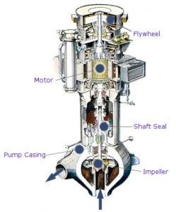
The main components of a reactor coolant pump
- Electric motor. The motor is a large, air or water (seal-less RCPs) cooled, induction motor.
- Impeller. Impeller is a rotor used to increase the pressure and flow of a coolant.
- Shaft (Rotor). Shaft is a mechanical component for transmitting torque from the motor to the impeller.
- Shaft seal package. Shaft seal package is used to prevent any water from leaking up the shaft into the containment.
- Bearings. Bearings constrain relative motion of the shaft (rotor) and reduce friction between the rotating shaft and the stator. RCPs usually use a combination of fluid dynamic bearings and hydrostatic bearings in the radial bearing assembly (water lubricated; close to the primary coolant) and oil lubricated bearings used in the thrust (axial) bearing assembly (in the motor section).
- Flywheel. The flywheel provides flow coastdown in case of loss of power.
- Auxilliary systems. Oil lubrication system, oil lift system, seal leakoff system, seal cooling system etc.
Use of shaft seals.
The seal package is located on the shaft between the electric motor and the impeller and prevents any primary coolant from leaking up the shaft into the containment. Any coolant that does leak up the shaft is collected and routed to the seal leakoff system.
- RCPs with shaft seals. In order to maintain pump pressure and restrict water volume loss, the pumps typically utilize a multi-stage mechanical face seal system. This configuration allows use of flywheel, which provides rotating inertia to ensure a slow decrease in coolant flow in order to prevent fuel damage as a result of a loss of power to the pump motors. An integrity of the pressure boundary in the event of a postulated flywheel failure has to be proved.
- Seal-less RCPs . This pumps do not have any shaft seals and any large flywheels. Entire RCP systems (motor, impeller, shaft, fluid bearings) are sealed at high pressure side of primary circuit. Such RCPs (Canned motor pumps) do not require so much external systems (no lube oil system, seal injection and leak-off system ) as the RCPs with shaft seals. These pumps can be more reliable, but sufficient rotating inertia (internal flywheels) to provide flow coastdown has to be proved.