Facebook Instagram Youtube Twitter

Reactor Coolant Pump

Reactor coolant pumps (RCPs) are used to pump primary coolant around the primary circuit. The purpose of the reactor coolant pump is to provide forced primary coolant flow to remove and transfer the amount of heat generated in the reactor core.

Nuclear power plants rely on cooling systems to ensure safe, continuous operation of the nuclear reactor. Cooling systems naturally ensure a heat transfer from a reactor core to steam generators, which is the main purpose of the cooling systems. Because of the large amount of heat generated in the reactor core by the fission reaction, the cooling systems demand a large volumetric flow of water (~80000 m3/hr) to ensure a sufficient and safe heat transfer. The cooling water is usually supplied by two or more large centrifugal pumps called reactor coolant pumps (RCPs). RCPs are not usually “safety system”, as defined. After the loss of RCPs the reactor must be shutdown immediately. Sufficient and safe residual heat removal is then ensured by a natural circulation flow through the reactor. However, natural circulation is not sufficient to remove the heat being generated when the reactor is at power.

Reactor Coolant PumpReactor coolant pumps (RCPs) are used to pump primary coolant around the primary circuit. The purpose of the reactor coolant pump is to provide forced primary coolant flow to remove and transfer the amount of heat generated in the reactor core. There are many designs of these pumps and there are many designs of primary coolant loops. There are significant differences between pumps for different reactor types. This article is focused on RCPs for pressurized water reactors. Most of  PWRs use four RCPs in two or four loops design.

Generally reactor coolant pumps are powerful, they can consume up to 6 MW each and therefore they can be used for heating the primary coolant before a reactor startup.

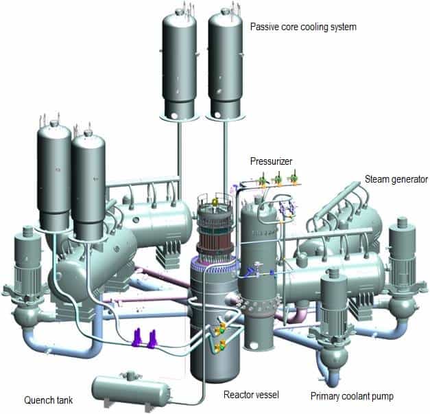
Most of  RCPs are vertical installed on a cold leg of a primary loop, but also a direct connection to a steam generator is possible. The reactor coolant enters the suction side of the pump at high pressure and temperature (~16MPa; 290°C; 554°F). The water is increased in velocity by the pump impeller. This increase in velocity is converted to pressure in the discharge volute. At the discharge of the reactor coolant pump, the reactor coolant pressure will be approximately 0,5MPa higher than the inlet pressure. After the coolant leaves the discharge side of the pump, it will enter the cold leg and continue to the reactor.  The coolant will then pass through the nuclear core and through the fuel, where collects heat and is sent back to the steam generators.

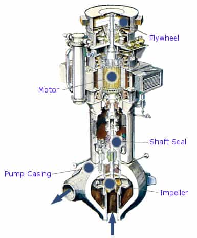
The main components of a reactor coolant pump

  • Electric motor. The motor is a large, air or water (seal-less RCPs) cooled, induction motor.
  • Impeller. Impeller is a rotor used to increase the pressure and flow of a coolant.
  • Shaft (Rotor). Shaft  is a mechanical component for transmitting torque from the motor to the impeller.
  • Shaft seal package. Shaft seal package is used to prevent any water from leaking up the shaft into the containment.
  • Bearings. Bearings constrain relative motion of the shaft (rotor) and reduce friction between the rotating shaft and the stator. RCPs usually use a combination of fluid dynamic bearings and hydrostatic bearings in the radial bearing assembly (water lubricated; close to the primary coolant) and oil lubricated bearings used in the thrust (axial) bearing assembly (in the motor section).
  • Flywheel. The flywheel provides flow coastdown in case of loss of power.
  • Auxilliary systems. Oil lubrication system, oil lift system, seal leakoff system, seal cooling system etc.

 Use of shaft seals.

The seal package is located on the shaft between the electric motor and the impeller and prevents any primary coolant from leaking up the shaft into the containment. Any coolant that does leak up the shaft is collected and routed to the seal leakoff system.

  • RCPs with shaft seals. In order to maintain pump pressure and restrict water volume loss, the pumps typically utilize a multi-stage mechanical face seal system. This configuration allows use of flywheel, which provides rotating inertia to ensure a slow decrease in coolant flow in order to prevent fuel damage as a result of a loss of power to the pump motors. An integrity of the pressure boundary in the event of a postulated flywheel failure has to be proved.
  • Seal-less RCPs . This pumps do not have any shaft seals and any  large flywheels. Entire  RCP systems (motor, impeller, shaft, fluid bearings) are sealed at high pressure side of primary circuit. Such RCPs (Canned motor pumps) do not require so much external systems (no lube oil system, seal injection and leak-off system ) as the RCPs with shaft seals. These pumps can be more reliable, but sufficient rotating inertia (internal flywheels) to provide flow coastdown has to be proved.

Pressurizer

A pressurizer is a component of a pressurized water reactor. Pressure in the primary circuit of PWRs is maintained by a pressurizer, a separate vessel that is connected to the primary circuit (hot leg) and partially filled with water which is heated to the saturation temperature (boiling point) for the desired pressure by submerged electrical heaters.
pressurizer
A pressurizer is a key component of PWRs.

Temperature in the pressurizer can be maintained at 350 °C (662 °F), which gives a subcooling margin (the difference between the pressurizer temperature and the highest temperature in the reactor core) of 30 °C. Subcooling margin is very important safety parameter of PWRs, since the boiling in the reactor core must be excluded. The basic design of the pressurized water reactor includes such requirement that the coolant (water) in the reactor coolant system must not boil. To achieve this, the coolant in the reactor coolant system is maintained at a pressure sufficiently high that boiling does not occur at the coolant temperatures experienced while the plant is operating or in an analyzed transient.

Gas Compression in Pressurizer
Pressure in the primary circuit of PWRs is maintained by a pressurizer, a separate vessel that is connected to the primary circuit (hot leg) and partially filled with water which is heated to the saturation temperature (boiling point) for the desired pressure by submerged electrical heaters. During the plant heatup the pressurizer can be filled by nitrogen instead of saturated steam.

Assume that a pressurizer contains 12 m3 of nitrogen at 20°C and 15 bar. The temperature is raised to 35°C, and the volume is reduced to 8.5 m3. What is the final pressure of the gas inside the pressurizer? Assume that the gas is ideal.

Solution:

Since the gas is ideal,we can use the ideal gas law to relate its parameters, both in the initial state i and in the final state f. Therefore:

pinitVinit = nRTinit

and

pfinalVfinal = nRTfinal

Dividing the second equation by the first equation and solving for pf we obtain:

pfinal = pinitTfinalVinit / TinitVfinal

Note that we cannot convert units of volume and pressure to basic SI units, because they cancel out each other. On the other hand we have to use Kelvins instead of degrees of Celsius. Therefore Tinit = 293 K and Tfinal = 308 K.

It follows, the resulting pressure in the final state will be:

pfinal = (15 bar) x (308 K) x (12 m3) / (293 K) x (8.5 m3) = 22 bar

Enthalpy of Water - 0.1 MPa, 3 MPa, 16 MPa
Latent heat of vaporization – water at 0.1 MPa (atmospheric pressure)

hlg = 2257 kJ/kg

Latent heat of vaporization – water at 3 MPa (pressure inside a steam generator)

hlg = 1795 kJ/kg

Latent heat of vaporization – water at 16 MPa (pressure inside a pressurizer)

hlg = 931 kJ/kg

See also: Enthalpy of Vaporization

Latent heat of vaporization - water at 0.1 MPa, 3 MPa, 16 MPa
The heat of vaporization diminishes with increasing pressure, while the boiling point increases. It vanishes completely at a certain point called the critical point.

Functions

Extensive vs. intensive thermodynamic properties
Extensive and intensive properties of medium in the pressurizer.

Pressure in the pressurizer is controlled by varying the temperature of the coolant in the pressurizer. For these purposes two systems are installed. Water spray system and electrical heaters system. Volume of the pressurizer (tens of cubic meters) is filled with water on saturation parameters and steam. The water spray system (relatively cool water – from cold leg) can decrease the pressure in the vessel by condensing the steam on water droplets sprayed in the vessel. On the other hand the submerged electrical heaters are designed to increase the pressure by evaporation the water in the vessel. Water pressure in a closed system tracks water temperature directly; as the temperature goes up, pressure goes up.

Over-pressure relief system

Part of the pressurizer system is an over-pressure relief system. In the event that pressurizer pressure exceeds a certain maximum, there is a relief valve called the pilot-operated relief valve (PORV) on top of the pressurizer which opens to allow steam from the steam bubble to leave the pressurizer in order to reduce the pressure in the pressurizer, thus leads to reduction of pressure in the whole system. This steam is routed to a large relief tank  in the reactor containment building where it is cooled and condensed back into liquid and stored for later disposition. There is a finite volume to these tanks and if events deteriorate to the point where the tanks fill up, a secondary pressure relief device on the tank(s), often a rupture disc, allows the condensed reactor coolant to spill out onto the floor of the reactor containment building where it pools in sumps for later disposition.

The pressurizer is equipped also with safety valves system (“safety system”), which are also routed to the relief tank. The safety valves system is used to emergency pressure reduction during emergency conditions.

Water level monitoring

Since the reactor coolant system is completely flooded during normal operations, there is no point in monitoring coolant level in any of the other vessels. But early awareness of a reduction of coolant level (or a loss of coolant) is very important to the safety of the reactor core. The pressurizer is deliberately located high in the reactor containment building such that, if the pressurizer has sufficient coolant in it, one can be reasonably certain that all the other vessels of the reactor coolant system (which are below it) are fully flooded with coolant. There is therefore, a coolant level monitoring system on the pressurizer and it is the one reactor coolant system vessel that is normally not full of coolant.

 Main components of pressurizer

  • Pressure vessel
  • Relief system. Consist of relief and safety valves and pressurized relief tank. The relief system is used to emergency pressure reduction during emergency conditions and the system.
  • Water spray system. Consist of spray nozzles and spray line. The water spray system is used to pressure reduction during normal conditions and the system is used to mixing the coolant inside the pressurizer.
  • Electrical heaters. The submerged electrical heaters are used to pressure increase during normal conditions.
  • Surge line nozzle. Connects the pressurizer with the primary circuit.
Nuclear reactor - WWER 1200
Nuclear reactor and primary coolant system of WWER-1200.
Source: http://www.bellona.ru/

Steam Generator

Steam generators are heat exchangers used to convert feedwater into steam from heat produced in a nuclear reactor core. The steam produced drives the turbine. They are used in the most nuclear power plants, but there are many types according to the reactor type. The boiling water reactor does not require steam generators since the water boils directly in the reactor core. In other types of reactors, such as the pressurised heavy water reactors of the CANDU design, the primary fluid is heavy water. Liquid metal cooled reactors such as the Russian BN-600 reactor also use heat exchangers between a secondary sodium circuit and a tertiary water circuit.

Design of Steam Generator

To increase the amount of heat transferred and the power generated, the heat exchange surface must be maximalized. This is obtained by using tubes. Each steam generator can contain anywhere from 3,000 to 16,000 tubes, each about  19mm diameter.While the secondary fluid is always water, the reactor coolant (carbon dioxide, sodium, helium) depends on the reactor type. Where the coolant is pressurized water, two solutions have been adopted. In the first of these, the secondary water flows through straight tubes welded to tubesheets at both ends. This is the “once-through” type of steam generator. To eliminate the loads exerted on the tubesheets by differential thermal expansion between outside shell and the tubes, a second solutions is often employed. This alternative gives acope for thermal expansion by using U-tubes welded to a single tubesheet. The tubes carry the pressurized primary coolant and are surrounded by the secondary water, which is turned into steam.

There are two designes for U-tubes steam generators. Design with tube bundle arranged vertically and design with tube bundle arranged horizontally. Horizontal steam generators are used in the VVER type reactors. In commercial power plants, there are 2 to 6 steam generators per reactor; each steam generator (vertical design) can measure up to 70 feet (~21m) in height and weigh as much as 800 tons.

The materials that make up the steam generators and tubes are specially made and specifically designed to withstand the heat, high pressure and radiation. The water tubes also have to be able to resist corrosion from water for an extended period of time.

Steam Generator - vertical
Steam Generator – vertical

Operating conditions

The hot primary coolant (water 330°C; 626°F; 16MPa) is pumped into the steam generator through primary inlet. High pressure of primary coolant is used to keep the water in the liquid state. Boiling of the primary coolant shall not occur. The liquid water flows through hundreds or thousands of tubes (usually 1.9 cm in diameter) inside the steam generator. The feedwater (secondary circuit) is heated from ~260°C 500°F to the boiling point of that fluid (280°C; 536°F; 6,5MPa). Heat is transferred through the walls of these tubes to the lower pressure secondary coolant located on the secondary side of the exchanger where the coolant evaporates to pressurized steam (saturated steam 280°C; 536°F; 6,5 MPa). The pressurized steam leaves the steam generator through a steam outlet and continues to the steam turbine. The transfer of heat is accomplished without mixing the two fluids to prevent the secondary coolant from becoming radioactive. The primary coolant leaves (water 295°C; 563°F; 16MPa) the steam generator through primary outlet and continues through a cold leg to a reactor coolant pump and then into the reactor.

See also: Steam Tables

Evaporation of water at high pressure - Energy balance in a steam generator
Steam Generator - vertical
Steam Generator – vertical

Calculate the amount of primary coolant, which is required to evaporate 1 kg of feedwater in a typical steam generator. Assume that there are no energy losses, this is only idealized example.

Balance of the primary circuit

The hot primary coolant (water 330°C; 626°F; 16MPa) is pumped into the steam generator through primary inlet. The primary coolant leaves (water 295°C; 563°F; 16MPa) the steam generator through primary outlet.

hI, inlet = 1516 kJ/kg

=> ΔhI = -206 kJ/kg

hI, outlet = 1310 kJ/kg

Balance of the feedwater

Steam generator - counterflow heat exchanger
Temperature gradients in typical PWR steam generator.

The feedwater (water 230°C; 446°F; 6,5MPa) is pumped into the steam generator through the feedwater inlet. The feedwater (secondary circuit) is heated from ~230°C 446°F to the boiling point of that fluid (280°C; 536°F; 6,5MPa). Feedwater is then evaporated and the pressurized steam (saturated steam 280°C; 536°F; 6,5 MPa) leaves the steam generator through steam outlet and continues to the steam turbine.

hII, inlet = 991 kJ/kg

=> ΔhII = 1789 kJ/kg

hII, outlet = 2780 kJ/kg

Balance of the steam generator

Since the difference in specific enthalpies is less for primary coolant than for feedwater, it is obvious that the amount of primary coolant will be higher than 1kg. To produce of 1 kg of saturated steam from feedwater, about 1789/206 x 1 kg =  8.68 kg of primary coolant is required.

Core inlet temperature
Core inlet temperature. Core inlet temperature is directly given by system parameters in steam generators. When steam generators are operated at approximately 6.0MPa, it means the saturation temperature is equal to 275.6 °C. Since there must be always ΔT (~15°C) between the primary circuit and the secondary circuit, the reactor coolant (in the cold leg)have about 290.6°C (at HFP) at the inlet of the core. As the system pressure increases, the core inlet temperature must also increase. This increase causes slight increase in fuel temperature.

Moisture separation

A moisture separation is important to maintain the moisture content of the steam as low as possible to prevent damage to the turbine blading. The vertical steam generators must use multiple stage moisture separation. The horizontal separators can use the moisture separation, but it is not necessary, since the steam releases the two phase fluid much more slowly and the produced steam is generally without moisture.

The vertical steam generators use usually two stages of moisture separation. One stage causes the mixture to spin, which slings the water to the outside. The water is then drained back to be used to make more steam. The drier steam is routed to the second stage of separation. In this stage, the mixture is forced to make rapid changes in direction. Because of the steam’s ability to change direction and the water’s inability to change, the steam exits the steam generator, and the water is drained back for reuse. The two stage process of moisture removal is so efficient at removing the water that for every 100 pounds of steam that exits the steam generator, the water content is less than 0.25 pounds.

Nuclear reactor - WWER 1200
Nuclear reactor and primary coolant system of WWER-1200.
Source: http://www.bellona.ru/